background image

Analog IN 2, Discrete 1, and Discrete 2 are not powered from switched power terminals. In this configuration, SP2 is

disabled. If you need SP2, contact the factory.

* Default positions

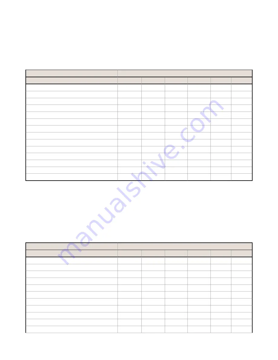
Discrete Configuration - Switch 2 ON (10V and 18V Boost Models)

The discrete configuration matches the switch power outputs (SP1, SP2) with the discrete inputs. The analog inputs are

disabled. The discrete configuration is selected when switch 2 is in the ON position.

Discrete Configuration, Switch 2 ON

DIP Switches

Descriptions

3

4

5

6

7

8

Discrete Inputs Sinking (NPN)

OFF*

Discrete Inputs Sourcing (PNP)

ON

Warm-up Time 5 milliseconds

OFF*

OFF*

Warm-up Time 10 milliseconds

OFF

ON

Warm-up Time 62.5 milliseconds

ON

OFF

Warm-up Time 125 milliseconds

ON

ON

Sample/Report Rate 62.5 milliseconds

OFF*

OFF*

OFF*

Sample/Report Rate 125 milliseconds

OFF

OFF

ON

Sample/Report Rate 250 milliseconds

OFF

ON

OFF

Sample/Report Rate 500 milliseconds

OFF

ON

ON

Sample/Report Rate 1 second

ON

OFF

OFF

Sample/Report Rate 2 seconds

ON

OFF

ON

Sample/Report Rate 16 seconds

ON

ON

OFF

Modbus or UCT configured (overrides DIP switches)

ON

ON

ON

Discrete IN 1 uses switched power 1 (SP1). Discrete IN 2 uses switched power 2 (SP2). Analog inputs 1 and 2 are

disabled.

* Default positions

Analog Configuration - Switch 2 OFF (18V Boost Models)

For analog configuration, DIP switch 2 is in the OFF position (factory default). Analog configuration has analog IN 1 linked

to switch power 1 (SP1) and is programmable using switches four through eight. Sample and report rates for analog input

2 are listed in the specifications. Discrete inputs 1 and 2 are also active in this configuration and the input types are

defined using switch 3.

Analog Configuration, Switch 2 OFF

DIP Switches

Descriptions

3

4

5

6

7

8

Discrete Inputs Sinking (NPN)

OFF*

Discrete Inputs Sourcing (PNP)

ON

Warm-up Time 20 milliseconds

OFF*

OFF*

Warm-up Time 2 seconds

OFF

ON

Warm-up Time 4 seconds

ON

OFF

Warm-up Time 8 seconds

ON

ON

Sample/Report Rate 4 second

OFF*

OFF*

OFF*

Sample/Report Rate 8 seconds

OFF

OFF

ON

Sample/Report Rate 16 seconds

OFF

ON

OFF

Sample/Report Rate 64 seconds

OFF

ON

ON

Sample/Report Rate 5 minutes

ON

OFF

OFF


SureCross DX99 FlexPower Node (Metal Housing)

4

www.bannerengineering.com - Tel: +1-763-544-3164

P/N 142497 Rev. L

Summary of Contents for DX99N9X1S2N0M2X0D2

Page 1: ...surecross Model Frequency Boost Voltage I O DX99N9X1S2N0M2X0D2 900 MHz ISM Band 18 V Discrete Mode Inputs Two selectable discrete Switch Power Two Configurable Analog Mode Inputs Two selectable discr...

Page 2: ...e Node s LED 1 flashes green to indicate it is communicating with the Gateway For one LED models the Gateway s LED is solid green and the Node s LED flashes green to indicate it is communicating with...

Page 3: ...iscrete configuration using the DIP switch specified in the table The default switch settings for this device are all in the OFF position Analog Configuration Switch 2 OFF 10V Boost Models For analog...

Page 4: ...conds ON ON OFF Modbus or UCT configured overrides DIP switches ON ON ON Discrete IN 1 uses switched power 1 SP1 Discrete IN 2 uses switched power 2 SP2 Analog inputs 1 and 2 are disabled Default posi...

Page 5: ...crosses the threshold setting For FlexPower applications setting the report rate to a slower rate extends the battery life Warm Up Time The warm up time defines how long the device must power up the...

Page 6: ...1 1 Node 16 Discrete IN 1 0 1 0 1 DI1 2 2 2 Node 16 Discrete IN 2 0 1 0 1 DI2 3 3 3 Node 16 Analog IN 1 mA or V 0 0 20 0 or 10 0 0 65535 A1 4 4 4 Node 16 Analog IN 2 mA or V 0 0 20 0 or 10 0 0 65535...

Page 7: ...Use of a different battery will VOID the intrinsic safety rating of this device and may result in an explosion When replacing the battery the negative end of the battery holder is the side with the s...

Page 8: ...d negative poles of the battery are positioned according to the markings on the board 4 Insert your sensor wires through a cable gland and one of the two 1 2 NPT ports Wire the sensor wires into the t...

Page 9: ...n Banner document 132607 7 Connect the end of your antenna cable to the supplied flexible antenna extension cable or to the antenna connector on the stainless steel antenna feedthrough The supplied fl...

Page 10: ...the housing and gently push down until the spacer frame pin holes rest on the edge of the metal housing 12 Close the metal cover firmly and lock closed using the set screw SureCross DX99 FlexPower Nod...

Page 11: ...esistant paint outside only Antenna Connection Ext Reverse Polarity SMA 50 Ohms Max Tightening Torque 0 45 N m 4 lbf in Interface Indicators Two bi color LEDs Buttons Two Display Six character LCD Wir...

Page 12: ...pack Flexible antenna cable terminal strip Metal Housing Accessories Model No Description List Price BWA HW 016 Antenna Feedthrough Stainless Steel 1 2 NPT 62 BWA HW 017 Antenna Feedthrough Stainless...

Page 13: ...pproved by Banner Engineering could void the user s authority to operate the product All specifications published in this document are subject to change Banner reserves the right to modify product spe...

Reviews: