background image

Analog Configuration, Switch 2 OFF

DIP Switches

Descriptions

3

4

5

6

7

8

Sample/Report Rate 15 minutes

ON

OFF

ON

Sample/Report Rate 30 minutes

ON

ON

OFF

Modbus or UCT configured (overrides DIP switches)

ON

ON

ON

Analog IN 2, Discrete 1, and Discrete 2 are not powered from switched power terminals. In this configuration, SP2 is

disabled. If you need SP2, contact the factory.

* Default positions

Discrete Input Type

Select the type of discrete input sensors to use with this device: sourcing (PNP) sensors or sinking (NPN) sensors.

Modbus/User Configuration Tool (UCT) or DIP Switch Configured

In Modbus/UCT Configured mode, the device parameters are changed using the User Configuration Tool (UCT) or a Modbus

command. All DIP switch positions are ignored. In DIP Switch Configured mode, use the DIP switches to configure the

parameters listed in the table.

Sample and Report Rates

The sample interval, or rate, defines how often the SureCross device samples the input. For battery-powered applications,

setting a slower rate extends the battery life.

The report rate defines how often the Node communicates the I/O status to the Gateway. Change of state reporting sets

the system to report only when the value crosses the threshold setting. For FlexPower

 applications, setting the report

rate to a slower rate extends the battery life.

Warm-Up Time

The warm-up time defines how long the device must power up the sensor before a stable sensor reading is taken.

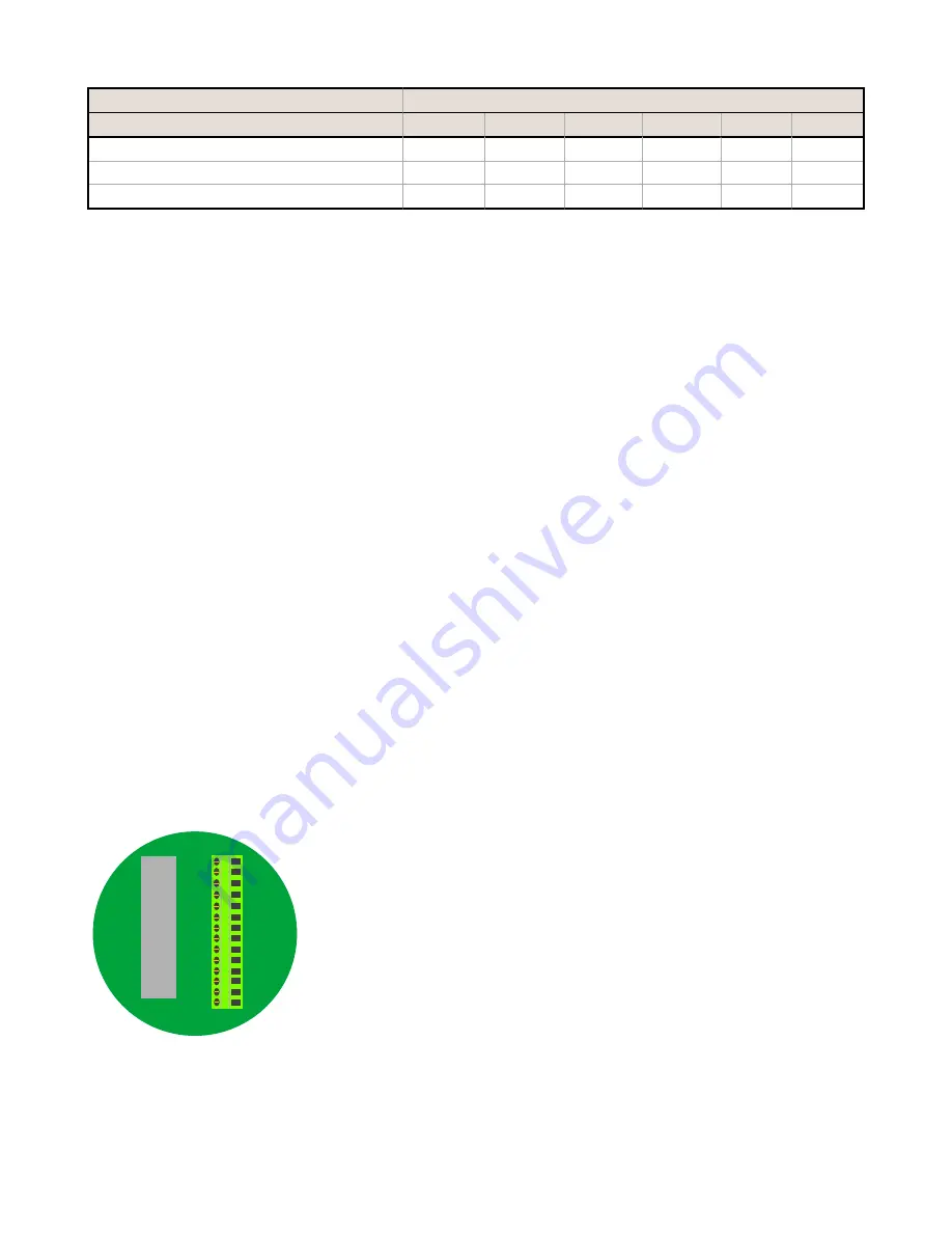
Terminal Blocks and Wiring

For CSA C/US and LCIE/ATEX approved wiring procedures and to check the Entity Parameters (Safety Parameters), refer

to the complete control drawing, document 

141513

 at 

www.bannerengineering.com

.

The GND connection can be considered the same as the housing ground when using a stainless steel antenna feedthrough

(model BWA-HW-016 or BWA-HW-017).

When the stainless steel antenna feedthroughs are not used, the GND connection is isolated from the metal housing.

BAT
GND
SP2
SP1
GND
DI2
GND

DI1
SP2
AI2
GND
SP1
AI1
GND

Ax+ and Ax–. Analog IN x. Analog inputs for devices requiring more

than one connection, such as thermocouples or RTDs. When there is

no Ax–, use Ax+ as an analog input.

DIx. Discrete IN x

GND. Ground/dc common connection

SPx. Switch Power; provides variable power sources for external

devices

LED Behavior for the Nodes

Nodes do not sample inputs until they are communicating with the Gateway. The radios and antennas must be a minimum

distance apart to function properly. Recommended minimum distances are:

SureCross DX99 FlexPower Node (Metal Housing)


P/N 142497 Rev. L

www.bannerengineering.com - Tel: +1-763-544-3164

5

Summary of Contents for DX99N9X1S2N0M2X0D2

Page 1: ...surecross Model Frequency Boost Voltage I O DX99N9X1S2N0M2X0D2 900 MHz ISM Band 18 V Discrete Mode Inputs Two selectable discrete Switch Power Two Configurable Analog Mode Inputs Two selectable discr...

Page 2: ...e Node s LED 1 flashes green to indicate it is communicating with the Gateway For one LED models the Gateway s LED is solid green and the Node s LED flashes green to indicate it is communicating with...

Page 3: ...iscrete configuration using the DIP switch specified in the table The default switch settings for this device are all in the OFF position Analog Configuration Switch 2 OFF 10V Boost Models For analog...

Page 4: ...conds ON ON OFF Modbus or UCT configured overrides DIP switches ON ON ON Discrete IN 1 uses switched power 1 SP1 Discrete IN 2 uses switched power 2 SP2 Analog inputs 1 and 2 are disabled Default posi...

Page 5: ...crosses the threshold setting For FlexPower applications setting the report rate to a slower rate extends the battery life Warm Up Time The warm up time defines how long the device must power up the...

Page 6: ...1 1 Node 16 Discrete IN 1 0 1 0 1 DI1 2 2 2 Node 16 Discrete IN 2 0 1 0 1 DI2 3 3 3 Node 16 Analog IN 1 mA or V 0 0 20 0 or 10 0 0 65535 A1 4 4 4 Node 16 Analog IN 2 mA or V 0 0 20 0 or 10 0 0 65535...

Page 7: ...Use of a different battery will VOID the intrinsic safety rating of this device and may result in an explosion When replacing the battery the negative end of the battery holder is the side with the s...

Page 8: ...d negative poles of the battery are positioned according to the markings on the board 4 Insert your sensor wires through a cable gland and one of the two 1 2 NPT ports Wire the sensor wires into the t...

Page 9: ...n Banner document 132607 7 Connect the end of your antenna cable to the supplied flexible antenna extension cable or to the antenna connector on the stainless steel antenna feedthrough The supplied fl...

Page 10: ...the housing and gently push down until the spacer frame pin holes rest on the edge of the metal housing 12 Close the metal cover firmly and lock closed using the set screw SureCross DX99 FlexPower Nod...

Page 11: ...esistant paint outside only Antenna Connection Ext Reverse Polarity SMA 50 Ohms Max Tightening Torque 0 45 N m 4 lbf in Interface Indicators Two bi color LEDs Buttons Two Display Six character LCD Wir...

Page 12: ...pack Flexible antenna cable terminal strip Metal Housing Accessories Model No Description List Price BWA HW 016 Antenna Feedthrough Stainless Steel 1 2 NPT 62 BWA HW 017 Antenna Feedthrough Stainless...

Page 13: ...pproved by Banner Engineering could void the user s authority to operate the product All specifications published in this document are subject to change Banner reserves the right to modify product spe...

Reviews: