background image

2.4 GHz 65 mW radios: 1 foot
900 MHz 150 mW radios: 6 feet
900 MHz 1 Watt radios: 15 feet
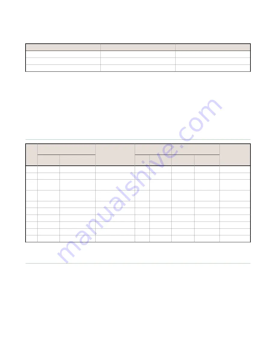
LED 1

LED 2

Node Status

Flashing green

Radio Link Ok

Flashing red

Flashing red

Device Error

Flashing red, 1 per 3 sec

No Radio Link

Storage Mode and Sleep Mode

While in storage mode, the radio does not operate. All SureCross

®

 radios powered from an integrated battery ship from

the factory in storage mode to conserve the battery. To wake the device, press and hold button 1 for 5 seconds. To put

any FlexPower

®

 or integrated battery SureCross radio into storage mode, press and hold button 1 for 5 seconds. The radio

is in storage mode when the LEDs stop blinking, but in some models, the LCD remains on for an additional minute after

the radio enters storage mode. After a device has entered storage mode, you must wait 1 minute before waking it.

During normal operation, the SureCross radio devices enter sleep mode after 15 minutes of operation. The radio

continues to function, but the LCD goes blank. To wake the device, press any button.

Modbus Register Table

I/O

Modbus Holding Register

I/O Type

I/O Range

Holding Register

Representation

Terminal Block

Labels

Gateway

Any Node

Min.

Max.

Min.

(Dec.)

Max. (Dec.)

1

1

1 + (Node# × 16)

Discrete IN 1

0

1

0

1

DI1

2

2

2 + (Node# × 16)

Discrete IN 2

0

1

0

1

DI2

3

3

3 + (Node# × 16)

Analog IN 1 (mA or

V)

0.0

20.0 or

10.0

0

65535

A1+

4

4

4 + (Node# × 16)

Analog IN 2 (mA or

V)

0.0

20.0 or

10.0

0

65535

A2+

...

7

7

7 + (Node# × 16)

Reserved

8

8

8 + (Node# × 16)

Device Message

...

15

15

15 + (Node# × 16) Control Message

16

16

16 + (Node# × 16) Reserved

Replacing the Battery (DX99...D Models)

To replace the lithium "D" cell battery in the metal housings, follow these steps.
1. Unscrew the lid of the metal enclosure.
2. Disconnect the radio by unplugging the ribbon cable from the radio board.

The radio board is mounted inside the metal lid.

3. Remove the discharged battery by pressing the battery towards the negative terminal to compress the spring. Pry up

on the battery’s positive end to remove from the battery holder.

4. Replace with a new battery. Only use a 3.6 V lithium battery from Xeno, model number XL-205F.
5. Verify the battery’s positive and negative terminals align to the positive and negative terminals of the battery holder

mounted within the case. Caution: There is a risk of explosion if the battery is replaced incorrectly.

6. Wait two minutes.
7. Plug the ribbon cable back into the radio board.
8. Screw on the lid and tighten.
9. After replacing the battery, allow up to 60 seconds for the device to power up.


SureCross DX99 FlexPower Node (Metal Housing)

6

www.bannerengineering.com - Tel: +1-763-544-3164

P/N 142497 Rev. L

Summary of Contents for DX99N9X1S2N0M2X0D2

Page 1: ...surecross Model Frequency Boost Voltage I O DX99N9X1S2N0M2X0D2 900 MHz ISM Band 18 V Discrete Mode Inputs Two selectable discrete Switch Power Two Configurable Analog Mode Inputs Two selectable discr...

Page 2: ...e Node s LED 1 flashes green to indicate it is communicating with the Gateway For one LED models the Gateway s LED is solid green and the Node s LED flashes green to indicate it is communicating with...

Page 3: ...iscrete configuration using the DIP switch specified in the table The default switch settings for this device are all in the OFF position Analog Configuration Switch 2 OFF 10V Boost Models For analog...

Page 4: ...conds ON ON OFF Modbus or UCT configured overrides DIP switches ON ON ON Discrete IN 1 uses switched power 1 SP1 Discrete IN 2 uses switched power 2 SP2 Analog inputs 1 and 2 are disabled Default posi...

Page 5: ...crosses the threshold setting For FlexPower applications setting the report rate to a slower rate extends the battery life Warm Up Time The warm up time defines how long the device must power up the...

Page 6: ...1 1 Node 16 Discrete IN 1 0 1 0 1 DI1 2 2 2 Node 16 Discrete IN 2 0 1 0 1 DI2 3 3 3 Node 16 Analog IN 1 mA or V 0 0 20 0 or 10 0 0 65535 A1 4 4 4 Node 16 Analog IN 2 mA or V 0 0 20 0 or 10 0 0 65535...

Page 7: ...Use of a different battery will VOID the intrinsic safety rating of this device and may result in an explosion When replacing the battery the negative end of the battery holder is the side with the s...

Page 8: ...d negative poles of the battery are positioned according to the markings on the board 4 Insert your sensor wires through a cable gland and one of the two 1 2 NPT ports Wire the sensor wires into the t...

Page 9: ...n Banner document 132607 7 Connect the end of your antenna cable to the supplied flexible antenna extension cable or to the antenna connector on the stainless steel antenna feedthrough The supplied fl...

Page 10: ...the housing and gently push down until the spacer frame pin holes rest on the edge of the metal housing 12 Close the metal cover firmly and lock closed using the set screw SureCross DX99 FlexPower Nod...

Page 11: ...esistant paint outside only Antenna Connection Ext Reverse Polarity SMA 50 Ohms Max Tightening Torque 0 45 N m 4 lbf in Interface Indicators Two bi color LEDs Buttons Two Display Six character LCD Wir...

Page 12: ...pack Flexible antenna cable terminal strip Metal Housing Accessories Model No Description List Price BWA HW 016 Antenna Feedthrough Stainless Steel 1 2 NPT 62 BWA HW 017 Antenna Feedthrough Stainless...

Page 13: ...pproved by Banner Engineering could void the user s authority to operate the product All specifications published in this document are subject to change Banner reserves the right to modify product spe...

Reviews: