background image

Pick-to-Light Solutions Guide

Instruction Manual

Original Instructions
214046 Rev. A
14 November 2019

©

 Banner Engineering Corp. All rights reserved

214046

Summary of Contents for DXM700

Page 1: ...Pick to Light Solutions Guide Instruction Manual Original Instructions 214046 Rev A 14 November 2019 Banner Engineering Corp All rights reserved 214046 ...

Page 2: ...est Mode 8 3 1 4 Clear Mode 8 3 2 Using the Read Write Registers Operation 8 3 2 1 Examples 9 4 Operating Modes 10 4 1 Teach Mode 11 4 2 Sequence Pick Mode 11 4 3 Batch Pick Mode 11 4 4 Host Load List 11 4 5 Compact List 12 4 6 File SbFile1 dat 12 5 Accessories 13 5 1 Cordsets 13 6 Product Support and Maintenance 15 6 1 Recommended Resources 15 6 2 Contact Us 15 6 3 Banner Engineering Corp Limited...

Page 3: ...wide variety of applications including assembly kitting and order fulfillment The four main states of a pick device are Figure 1 PTL110 Pick to Light Sensor Wait State The device is either inactive or the bin is not selected in the current pick group default color and animation off Mispick State While in Wait State when the primary or secondary sensor becomes active the state changes to Mispick af...

Page 4: ... configure them spontaneously Allows for a sequential or batch picking mode Easily assign Device IDs with flexibility for moves adds and changes Touch and optical sensor interactions can be uniquely identified to provide dual functionality 1 4 Solution Components 1 4 1 DXM700 Figure 3 DXM700 B1 PTL The DXM700 Controller with the ScriptBasic Solution completes all of the low level logic for a Pick ...

Page 5: ... mW PE5 Performance Radio Worldwide R4 2 4 GHz 65 mW HE5 MultiHop Data Radio Worldwide R5 900 MHz 65 mW HE5L MultiHop Data Radio Used for M GAGE networks PTL Pre Programmed DXM700 for Pick to Light Integration Reference the following documents for further information about the DXM700 DXM700 B1 Wireless Controller Datasheet Original document PN 207893 DXM700 Bx Wireless Controller Instruction Manua...

Page 6: ...tor only QP150 Dual 150 mm PVC cable with 4 pin M12 Euro style quick disconnects QP150 Connection Touch Models not connected in a series with a quick disconnect require a mating cordset Housing S PICK IQ Serial Communication Control 110 S QPS150 Dual 150 mm PVC shielded cable with 5 pin M12 Euro style quick disconnects Note Address initialization requires a touch sensor Adding the display option a...

Page 7: ...s confirmation of the connection on the bottom toolbar 7 Upload the PTL110 file by going to the Upload Script Settings screen Click Upload File and select the file 8 Select the uploaded file in the window to the right of the Upload Script button Click Add Selected to Startup The DXM700 runs this script every time it restarts 9 Save the XML file using the File Save menu Note The tool does not autos...

Page 8: ...e first device to assign the first ID When a device is selected the color for that device changes to green 5 Touch the sensor on the next device The controller assigns the next ID to that device The process continues until all devices are assigned IDs 3 1 3 Connectivity Test Mode 1 Set DXM Local Register 851 Initialization Mode to a value of 3 to trigger the DXM Controller to quickly flash each Pi...

Page 9: ...hrough RdData10 Registers 714 723 Registers 701 702 and 703 keep the previous values so writing a 13 into RdWrDID 700 writes to the next device The program changes the DID from 13 to 0 zero when complete and places the data in 714 723 How to Write Wait Mode Settings with Device ID 8 To read registers 6302 through 6311 1 Write a 1 one into RdWrFunction register 701 for Write 2 Write a 6302 into RdW...

Page 10: ...ice in the network 12 List Entry n Count Defines the count value associated to the previous Device ID The count can be the display on the LED display or encoded in the flash pattern for the device 13 List Entry n 1 DID Entry N 1 on the list 14 List Entry n 1 Count Entry N 1 on the list Operating Mode Local Register Value Description Teach Mode 5 1 Set DXM Local Register 5 Operation Mode to a value...

Page 11: ...from the host not the SD card set DXM Local Register 6 Run Host List to a value of 1 This starts the Pick to Light sequence The list is in DXM Local Registers 11 Register 11 contains the first Device ID in the sequence and Register 12 contains the count associated to the first Device ID Each subsequent device on the list is stored in DXM Local Registers requiring two Local Registers for each devic...

Page 12: ...t directory of the DXM local SD card An example of the file is shown below All values are separated by a comma The first entry on the line is the List ID and the last entry on a line is an E indicating the end of the list The in between value pairs define the Device ID and Count for each pick The Device ID is the Pick to Light identifier given to a device when it is commissioned in the network The...

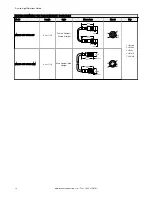
Page 13: ...ft MQDC 430 9 14 m 30 ft MQDC 450 15 2 m 50 ft MQDC 406RA 1 83 m 6 ft Right Angle 32 Typ 1 26 30 Typ 1 18 ø 14 5 0 57 M12 x 1 MQDC 415RA 4 57 m 15 ft MQDC 430RA 9 14 m 30 ft MQDC 450RA 15 2 m 50 ft 4 Pin Threaded M12 Euro Style Cordsets Double Ended Model Length Style Dimensions Pinout MQDEC 401SS 0 31 m 1 ft Male Straight Female Straight 40 Typ 1 58 ø 14 5 0 57 M12 x 1 44 Typ 1 73 ø 14 5 0 57 M12...

Page 14: ...1 ft Female Straight Female Straight 44 mm max ø 14 5 M12 x 1 44 mm max ø 14 5 M12 x 1 2 3 4 1 5 1 Brown 2 White 3 Blue 4 Black 5 Shield MQDEC STP 501SS MM 0 3 m 1 ft Male Straight Male Straight M12 x 1 ø 14 5 M12 x 1 ø 14 5 40 mm max 40 mm max 1 4 5 3 2 Pick to Light Solutions Guide 14 www bannerengineering com Tel 1 888 373 6767 ...

Page 15: ...version of any documentation refer to www bannerengineering com For patent information see www bannerengineering com patents 6 4 Banner Engineering Corp Software Copyright Notice This software is protected by copyright trade secret and other intellectual property laws You are only granted the right to use the software and only for the purposes described by Banner Banner reserves all other rights i...

Page 16: ...ent generates uses and can radiate radio frequency energy and if not installed and used in accordance with the instructions may cause harmful interference to radio communications However there is no guarantee that interference will not occur in a particular installation If this equipment does cause harmful interference to radio or television reception which can be determined by turning the equipme...

Reviews: