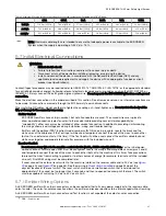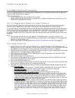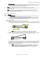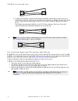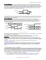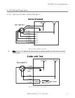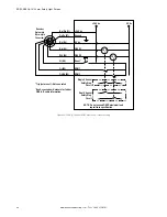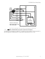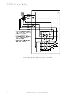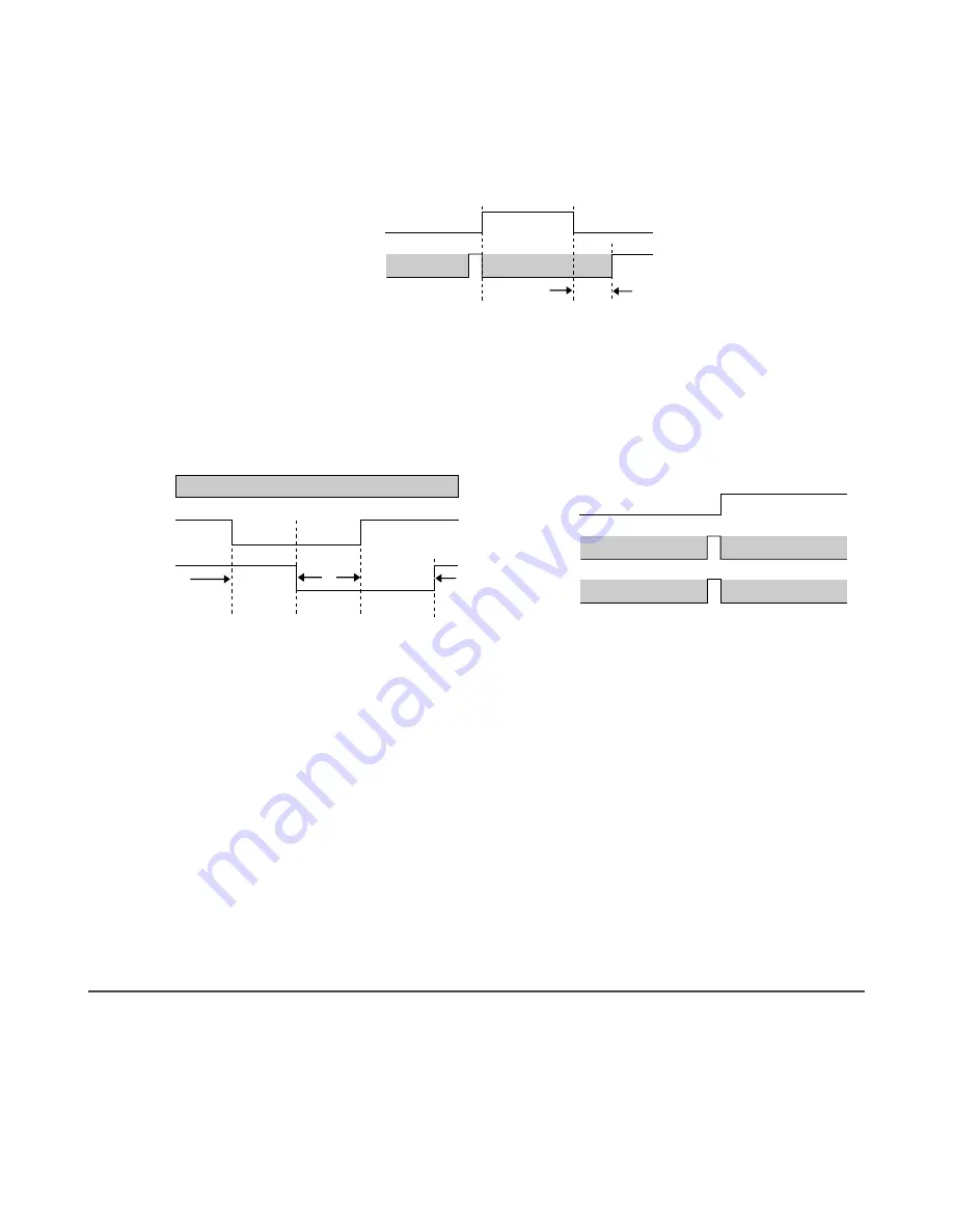
One-Channel Monitoring: This is a series connection of closed monitor contacts that are forced-guided (mechanically
linked) from each device controlled by the EZ-SCREEN. The monitor contacts must be closed before the EZ-SCREEN can
be reset and the OSSDs can turn ON. After a reset is executed and the safety outputs (OSSDs) turn ON, the status of the
monitor contacts are no longer monitored and may change state. However, the monitor contacts must be closed within 250
milliseconds of the OSSD outputs going from ON to OFF. Refer to
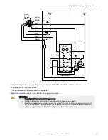
on page 43 for wiring. Connect the
monitor contacts b24 V dc and EDM (orange wire, pin 9).
Safety Output
Closed
Open
OFF
ON
EDM
Don’t Care
Don’t Care
Don’t Care
Don’t Care
250 ms
Max.
250 ms
Max.
250 ms
Max.
For EZ-SCREEN receivers with a date code prior to 0834, the monitoring contacts must open within 200 milliseconds of the
OSSD outputs turning ON (a clear condition) and must close within 200 milliseconds of the OSSD outputs turning OFF (a
blocked condition) or a lockout will occur.
Two-Channel Monitoring: This is an independent connection of closed monitor contacts that are forced-guided
(mechanically linked) from each device controlled by the EZ-SCREEN. The monitor contacts must be closed before the EZ-
SCREEN can be reset and the OSSDs can turn ON. Regardless of the state of the OSSDs, the monitor contacts may
change state (either both open, or both closed). If the monitor contacts remain in opposite states for more than 250
milliseconds, a lockout occurs.
Safety Output
250 ms
Max.
250 ms
Max.
250 ms
Max.
250 ms
Max.
250 ms
Max.
250 ms
Max.
Don’t Care
Closed
Open
Closed
Open
EDM 1
EDM 2
Safety Output
Closed
Open
Closed
Open
OFF
ON
EDM 1
EDM 2
Must Match EDM 1
Must Match EDM 1
Must Match EDM 2
Must Match EDM 2
Must Match EDM 1
Must Match EDM 1
Must Match EDM 2
Must Match EDM 2
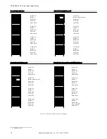
Figure 16. 2-Channel EDM Wiring
Refer to the figures above for 2-channel EDM wiring. Connect the monitor contacts as shown b24 V dc and EDM1
(pin 3) and b24 V dc and EDM2 (pin 2).
For EZ-SCREEN receivers with a date code prior to 0834, the monitoring contacts must always close within 200
milliseconds of the corresponding OSSD state change (turning OFF) or a lockout will occur.
No Monitoring: Use this configuration to perform the initial checkout; see
If the
application does not require the EDM function, it is the user's responsibility to ensure that this configuration does not create
a hazardous situation.
To configure the System for No monitoring, jumper EDM1 (orange wire, pin 3) to EDM2 (orange/black
wire, pin 2).
Refer to
on page 45 for “no monitoring” wiring. Set the configuration DIP switch to E2, per
An alternate method to configure no monitoring is to set the configuration DIP switch to E1 (1-channel monitoring), per
on page 48, and connect EDM1 (orange wire, pin 3) to +24 V dc. This method allows the
ability to use the auxiliary output (see
on page 41) in applications that do not require the EDM
function.
5.10 Auxiliary (Aux.) Output
An aux. output function is available when the receiver is configured for 1-channel EDM (for receivers with date code 0834 or
newer). This current sourcing (PNP) solid-state output (75 mA maximum) is used for control functions that are not safety
related. A typical use is to signal the state of the OSSDs to a programmable logic controller (PLC). The aux. output follows
the state of the OSSDs. Pin 2 (orange/black) supplies the connection; see
Generic Emitter Wiring Diagram
on page 43.
To use the auxiliary output in an application configured for no monitoring:
1. Set the configuration DIP switch to E1 (1-channel monitoring) per
on page 48.
2. Connect EDM1 (pin 3) to +24 V dc (see
Machine Primary Control Elements and EDM Input
on page 40).
EZ-SCREEN
®
14/30 mm Safety Light Screen
www.bannerengineering.com - Tel: + 1 888 373 6767
41

