4. Verify that:
• Access to any dangerous parts of the guarded machine is not possible from any direction not protected by
the EZ-SCREEN System, hard (fixed) guarding, or supplemental safeguarding, and
• It is not possible for a person to stand between the defined area and the dangerous parts of the machine, or
• Supplemental safeguarding and hard (fixed) guarding, as described by the appropriate safety standards, are
in place and functioning properly in any space (between the defined area and any hazard) which is large
enough to allow a person to stand undetected by the EZ-SCREEN.
5. If used, verify that all reset switches are mounted outside and in full view of the guarded area, out of reach of
anyone inside the guarded area, and that means of preventing inadvertent use is in place.
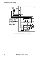
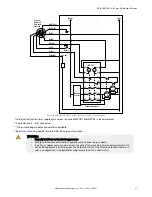
6. Examine the electrical wiring connections between the EZ-SCREEN OSSD outputs and the guarded machine’s
control elements to verify that the wiring meets the requirements stated in
Electrical Connections to the Guarded
on page 38.
7. Inspect the area near the defined area (including work pieces and the guarded machine) for reflective surfaces (see
on page 25). Remove the reflective surfaces if possible by relocating them, painting,
masking or roughening them. Remaining problem reflections will become apparent during the Trip Test.
8. Verify that power to the guarded machine is Off. Remove all obstructions from the defined area. Apply power to the
EZ-SCREEN System. If the EZ-SCREEN is configured for Manual Power-Up, the amber Status indicator will be
double-flashing. Perform a manual reset (close the reset switch for 0.25 to 2 seconds, then open the switch).
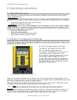
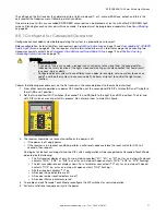
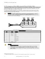
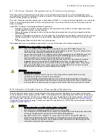
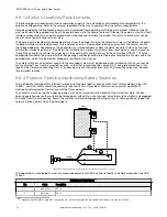
9. Observe the Status indicators and Diagnostic Display:
• Lockout: Status flashing red; all others Off
• Blocked: Status On red; one or more Zone indicators On red; Reset On amber
• Clear: Status On green
10
; all Zone indicators On green; Reset On amber
• Latch: (defined area clear) Status On red; all Zone indicators On green; Reset double-flashing amber
10. A Blocked condition indicates that one or more of the beams is misaligned or interrupted. See the Optical Alignment
procedure in the
on page 32 section to correct this situation. If the System is in a Latch
condition, perform a manual reset.
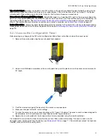
11. After the green and amber Status indicators are On, perform the trip test (in the
32 section) on each sensing field to verify proper System operation and to detect possible optical short circuits or
reflection problems. Do not continue until the EZ-SCREEN passes the trip test.
Important: Do not expose any individual to any hazard during the following checks.
WARNING:
• Clear the guarded area before applying power or resetting the system
• Failure to clear the guarded area before applying power could result in serious injury or
death.
• Verify that the guarded area is clear of personnel and any unwanted materials before
applying power to the guarded machine or before resetting the system.
12. Apply power to the guarded machine and verify that the machine does not start up.
13. Interrupt (block) the defined area with the appropriate supplied test piece and verify that it is not possible for the
guarded machine to be put into motion while the beam(s) is blocked.
14. Initiate machine motion of the guarded machine and, while it is moving, use the supplied test piece to block the
defined area. Do not attempt to insert the test piece into the dangerous parts of the machine. Upon blocking any
beam, the dangerous parts of the machine must come to a stop with no apparent delay.
15. Remove the test piece from the beam; verify that the machine does not automatically restart, and that the initiation
devices must be engaged to restart the machine.
16. Remove electrical power to the EZ-SCREEN. Both OSSD outputs should immediately turn Off, and the machine
must not be capable of starting until power is re-applied to the EZ-SCREEN.
17. Test the machine stopping response time, using an instrument designed for that purpose, to verify that it is the
same or less than the overall system response time specified by the machine manufacturer.
Do not continue operation until the entire checkout procedure is complete and all problems are corrected.
10
The status indicator flashes green if reduced resolution is enabled.
EZ-SCREEN
®
14/30 mm Safety Light Screen
60
www.bannerengineering.com - Tel: + 1 888 373 6767

