5.2.4 Supplemental Safeguarding
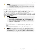
Properly position the EZ-SCREEN such that an individual
cannot reach through the defined area and access the hazard
point before the machine has stopped.
Additionally, the hazard cannot be accessible by reaching
around, under, or over the defined area. To accomplish this,
supplemental guarding (mechanical barriers, such as screens
or bars), as described by ANSI B11.19 safety requirements or
other appropriate standards, must be installed. Access will
then be possible only through the defined area of the EZ-
SCREEN System or through other safeguarding that prevents
access to the hazard (see
on page 24).
The mechanical barriers used for this purpose are typically
called "hard (fixed) guarding"; there must be no gaps between
the hard (fixed) guarding and the defined area. Any openings in
the hard (fixed) guarding must comply with the safe opening
requirements of ANSI B11.19 or other appropriate standard.
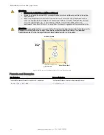
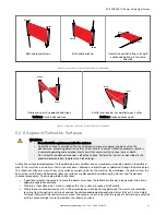
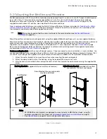
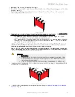
Hard (fixed) Guarding
Reset Switch
Conveyor
Opening
Area
Guarding
Robot
Turn-
Table
Hard (fixed)
Guarding
Area
Guarding
Safety Light Curtain/Screen
Figure 4. An example of supplemental safeguarding
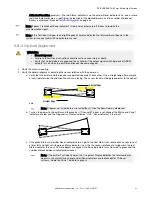
conjunction with the hard (fixed) guarding, is the primary safeguard. Supplemental safeguarding (such as a horizontal-
mounted safety light screen as an area guard) is required in areas that cannot be viewed from the reset switch (for example,
behind the robot and the conveyor). Additional supplemental safeguarding may be required to prevent clearance or trapping
hazards (for example, a safety mat as an area guard between the robot, the turntable, and the conveyor).
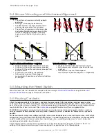
WARNING:
• The hazard must be accessible only through the sensing field
• Incorrect system installation could result in serious injury or death.
• The installation of the EZ-SCREEN must prevent any individual from reaching around, under, over
or through the defined area and into the hazard without being detected.
• See OSHA CFR 1910.217, ANSI B11.19, and/or ISO 14119, ISO 14120 and ISO 13857 for
information on determining safety distances and safe opening sizes for your guarding device.
Mechanical barriers (for example, hard (fixed) guarding) or supplemental safeguarding might be
required to comply with these requirements.
5.2.5 Emitter and Receiver Orientation
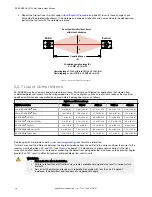
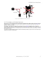
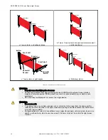
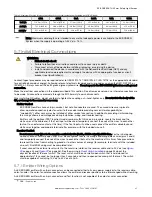
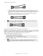
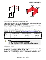
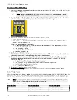
The emitter and receiver must be mounted parallel to each other and aligned in a common plane, with both machine
interface cable ends pointing in the same direction. Never mount the emitter with its machine interface cable end oriented in
the opposite direction of the cable end of the receiver. If this occurs, voids in the light screen may allow objects or
personnel to pass through the defined area undetected.
The emitter and receiver may be oriented in a vertical or horizontal plane, or at any angle between horizontal and vertical, as
long as they are parallel to each other and their cable ends point in the same direction. Verify that the light screen
completely covers all access to the hazard point that is not already protected by hard (fixed) guarding or other supplemental
guarding.
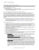
WARNING:
• Properly install system components
• Incorrectly orienting the system components impairs the performance of the system and results
in incomplete guarding, which can result in serious injury or death.
• Install the system components with their corresponding cable ends pointing in the same
direction.
EZ-SCREEN
®
14/30 mm Safety Light Screen
24
www.bannerengineering.com - Tel: + 1 888 373 6767


