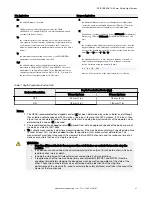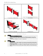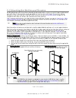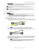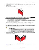
Receiver
Emitter
Scan Code 2
Receiver
Emitter
Scan Code 1
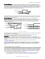
a. Two systems in a horizontal plane
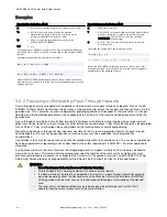
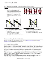
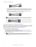
Receiver
Emitter
Scan Code 2
Receiver
Emitter
Scan Code 1
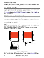
b. Two or three systems stacked (or alternate receiver/
emitter positions)
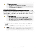
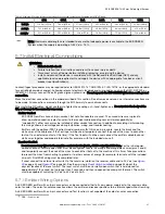
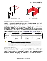
Emitter
Receiver
Horizontal
Receiver
Horizontal
Emitter
Scan Code 1
Scan Code 2
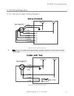
c. Two systems at right angles
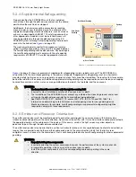
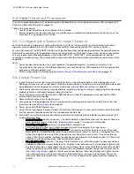
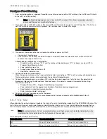
Receiver 1
Emitter 1
Scan Code 1
Receiver 2
Emitter 2
Scan Code 2
Receiver 3
Emitter 3
Scan Code 2
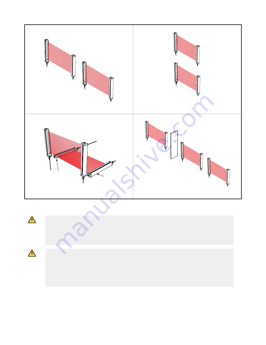
Opaque Shield
d. Multiple systems
Figure 9. Installation of Multiple Systems
WARNING:
• Properly connect multiple pairs of sensors
• Connecting multiple output signal switching devices (OSSD) safety outputs to one interface
module or otherwise parallel OSSD outputs can result in serious bodily injury or death, and is
prohibited.
• Do not connect multiple pairs of sensors to a single device.
WARNING:
• Use a scan code
• If you do not use a scan code, a receiver can synchronize to the signal from the wrong emitter,
reducing the safety function of the light screen and creating an unsafe condition that could result
in serious injury or death.
• Configure adjacent systems to use different scan codes (for example, set one system to use scan
code 1 and the other system to use scan code 2). Perform a trip test to confirm the light screen
function.
EZ-SCREEN
®
14/30 mm Safety Light Screen
28
www.bannerengineering.com - Tel: + 1 888 373 6767


