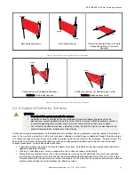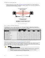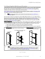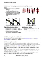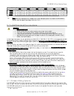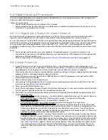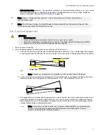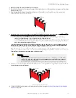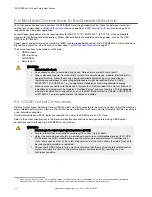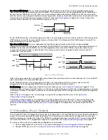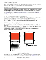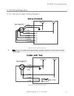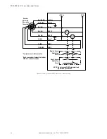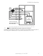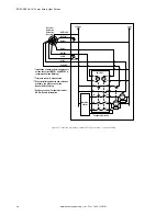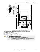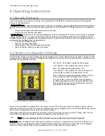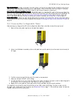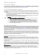
Figure 12. Optical alignment using the LAT-1-SS
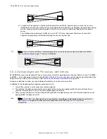
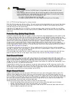
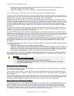
Component 2 (Mirror)
Component 3 (Mirror)
Component 4 (Receiver)
Component 1 (Emitter)
Figure 13. Corner Mirror Alignment
5.8.5 Reduced Resolution/Floating Blanking
Reduced Resolution increases the minimum diameter of an object that the light screen can reliably detect anywhere within
its defined area. Reduced Resolution is generally used to allow one or more objects (usually workpiece materials) to move
anywhere through the defined area, without tripping the OSSD safety outputs.
Enabling two-beam Reduced Resolution reduces the overall minimum object sensitivity, which allows multiple objects to
move through the defined area. The effect is that any two consecutive beams (except for the sync beam) can be blocked,
without causing the OSSDs to turn OFF. This is also called “Multiple-Point Floating Blanking.”
Multiple “holes” are created in which 14 mm systems detect a 30 mm object and ignore an 8.5 mm object. Similarly, 30 mm
systems detect a 60 mm object and ignore a 17 mm object. See the DIP-switch configuration. During operation, the Status
indicator flashes green when reduced resolution is enabled.
In reduced resolution applications, the separation distance always increases because of the larger depth penetration factor
(Dpf). In either case, calculate the separation distance (see
Calculating the Safety Distance (Minimum Distance)
on page 19.
Model
Reduced Resolution Setting
Maximum Size of Undetected Objects
Resulting Resolution
14 mm Resolution
Off
(Not applicable)
14 mm (0.55 in)
On (2-beam)
8.5 mm (0.34 in)
30 mm (1.18 in)
30 mm Resolution
Off
(Not applicable)
30 mm (1.18 in)
On (2-beam)
17 mm (0.67 in)
60 mm (2.36 in)
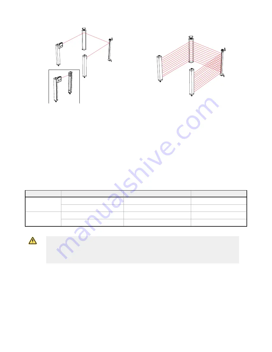
WARNING:
• Use reduced resolution and fixed blanking only when necessary
• Failure to follow these instructions could result in serious injury or death.
• Completely fill any holes created in the sensing field with the blanked object or increase the
safety (minimum) distance to account for the larger resolution.
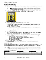
5.8.6 Fixed Blanking
Fixed blanking allows for a stationary object(s), such as tooling, to be ignored while it remains positioned within the defined
area. A flashing green Zone indicator denotes the location of a blanked area. If the object is moved or removed, the System
enters lockout mode so that an unexpected hole in the sensing field is not created.
One or multiple areas within an EZ-SCREEN sensor pair may be blanked out. The minimum number of beams between two
blanked areas is one. Any beam other than the sync beam may be blanked. All beams of a fixed blanked area must stay
blocked at all times (after the fixed blanking configuration mode has been exited), for the OSSDs to stay ON.
EZ-SCREEN
®
14/30 mm Safety Light Screen
www.bannerengineering.com - Tel: + 1 888 373 6767
35

