8.7 Emergency Stop Buttons and Rope/Cable Pulls
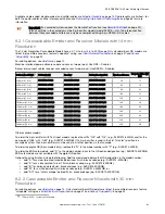
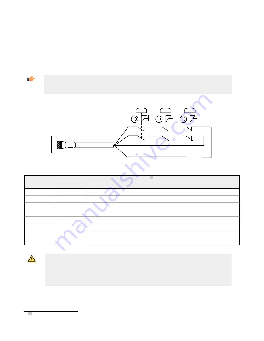
Cascadeable EZ-SCREEN receivers may be connected to one or more emergency stop buttons. Connect the button(s) to
the end of the last receiver in the cascade, in place of the terminator plug. The connected e-stop button(s) will activate/
deactivate the OSSD outputs in all receivers in the cascade.
The number of e-stop buttons allowed in a series connection is limited by the total resistance per channel. The total
resistance is the sum of all contact resistance values in the channel, plus the total wire resistance in the channel. The
maximum total resistance per channel is 100 Ohms.
Important: The simultaneity between the two e-stop contacts, on opening and closing, is 3 seconds. If
simultaneity is not met on either opening or closing, the first receiver’s display flashes “|- - -|.” If
simultaneity is not met on opening, the closed contact can be opened later (after more than 3 seconds),
then both contacts must be closed again.
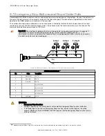
bn
wh
bu
bk
E-stop 1
E-stop 2
E-stop N
22 awg
Figure 29. Wiring of emergency stop buttons to the last receiver in the cascade.
QDE2R4-8..D Cable Pinout 16
Pin
Color
Description
1
brown (bn)
Ch 1a
2
black (bk)
Ch 1b
3
blue (bu)
Ch 2b
4
no connection
5
no connection
6
no connection
7
no connection
8
white (wh)
Ch 2a
WARNING:
• Emergency Stop Functions
• Muting or bypassing the safety outputs will render the Emergency Stop function ineffective.
• If Cascade Input is used for an Emergency Stop function, do not mute or bypass the safety
outputs (OSSDs) of the EZ-SCREEN. NFPA79 requires that the Emergency Stop function remain
active at all times.
16 Standard 8-pin M12/Euro-style QD cordsets can also be used, although the pin numbers and wire colors must be verified.
EZ-SCREEN
®
14/30 mm Safety Light Screen
72
www.bannerengineering.com - Tel: + 1 888 373 6767


