background image

10 Product Support and Maintenance

10.1 Cleaning

EZ-SCREEN components are constructed of aluminum with a yellow painted finish and are rated IEC IP65. Lens covers are

acrylic. Components are best cleaned using mild detergent or window cleaner and a soft cloth. Avoid cleaners containing

alcohol, as they may damage the acrylic lens covers.

10.2 Warranty Service

Contact Banner Engineering for troubleshooting of this device. Do not attempt any repairs to this Banner device; it contains

no field-replaceable parts or components. If the device, device part, or device component is determined to be defective by

a Banner Applications Engineer, they will advise you of Banner's RMA (Return Merchandise Authorization) procedure.

Important: If instructed to return the device, pack it with care. Damage that occurs in return shipping is

not covered by warranty.

10.3 Manufacturing Date

Every EZ-SCREEN produced is marked with a code that defines the week and year of manufacture and manufacturing

location. The code format (U.S. Standard format) is: YYWWL

• YY = Year of manufacture, 2 digits

• WW = Week of manufacture, 2 digits

• L = Banner-specific code, 1 digit

Example: 1809H = 2018, Week 9.

10.4 Disposal

Devices that are no longer in use should be disposed of according to the applicable national and local regulations.

10.5 Contact Us

Banner Engineering Corporate headquarters is located at:

9714 Tenth Avenue North

Minneapolis, MN 55441, USA

Website: 

www.bannerengineering.com

Phone: + 1 888 373 6767

For worldwide locations and local representatives, visit 

www.bannerengineering.com

.

10.6 Banner Engineering Corp Limited Warranty

Banner Engineering Corp. warrants its products to be free from defects in material and workmanship for one year following

the date of shipment. Banner Engineering Corp. will repair or replace, free of charge, any product of its manufacture which,

at the time it is returned to the factory, is found to have been defective during the warranty period. This warranty does not

cover damage or liability for misuse, abuse, or the improper application or installation of the Banner product.
THIS LIMITED WARRANTY IS EXCLUSIVE AND IN LIEU OF ALL OTHER WARRANTIES WHETHER EXPRESS OR IMPLIED

(INCLUDING, WITHOUT LIMITATION, ANY WARRANTY OF MERCHANTABILITY OR FITNESS FOR A PARTICULAR

PURPOSE), AND WHETHER ARISING UNDER COURSE OF PERFORMANCE, COURSE OF DEALING OR TRADE USAGE.
This Warranty is exclusive and limited to repair or, at the discretion of Banner Engineering Corp., replacement. IN NO

EVENT SHALL BANNER ENGINEERING CORP. BE LIABLE TO BUYER OR ANY OTHER PERSON OR ENTITY FOR ANY

EXTRA COSTS, EXPENSES, LOSSES, LOSS OF PROFITS, OR ANY INCIDENTAL, CONSEQUENTIAL OR SPECIAL

DAMAGES RESULTING FROM ANY PRODUCT DEFECT OR FROM THE USE OR INABILITY TO USE THE PRODUCT,

EZ-SCREEN

®

 14/30 mm Safety Light Screen


82

www.bannerengineering.com - Tel: + 1 888 373 6767


Summary of Contents for EZ-SCREEN

Page 1: ...EZ SCREEN 14 30 mm Safety Light Screen Instruction Manual Original Instructions 112852 Rev J 8 May 2019 Banner Engineering Corp All rights reserved 112852 ...

Page 2: ...anical Installation Considerations 19 5 2 1 Calculating the Safety Distance Minimum Distance 19 5 2 2 Reducing or Eliminating Pass Through Hazards 22 5 2 3 Reset Switch Location 23 5 2 4 Supplemental Safeguarding 24 5 2 5 Emitter and Receiver Orientation 24 5 2 6 Adjacent Reflective Surfaces 25 5 2 7 Use of Corner Mirrors 26 5 2 8 Installation of Multiple Systems 27 5 3 Mounting the Emitter and Re...

Page 3: ...3 Cascade Configuration vs Response Time 69 8 6 Cascaded Sensor Configuration Settings 70 8 6 1 Configure for Cascaded Operation 71 8 7 Emergency Stop Buttons and Rope Cable Pulls 72 8 7 1 E Stop Switch Requirements Positive Opening 73 8 8 Interlock Switches in Cascaded Systems 73 8 8 1 Interlock Guarding Requirements 74 8 8 2 Positive Opening Interlocking Safety Switches 74 8 8 3 Monitoring Serie...

Page 4: ...itch 89 12 7 Lens Shields 89 12 8 Tubular Enclosures 90 12 9 MSA Series Stands 90 12 10 MSM Series Corner Mirrors 91 12 11 SSM Series Corner Mirrors 91 12 12 Mounting Brackets 92 12 13 Alignment Aids 93 12 14 EZ LIGHT for EZ SCREEN 93 13 Glossary 95 EZ SCREEN 14 30 mm Safety Light Screen ...

Page 5: ...s Verify that the entire safeguarding system including input devices control systems and output devices is properly configured and installed operational and working as intended for the application Periodically re verify as needed that the entire safeguarding system is working as intended for the application 1 2 Use of Warnings and Cautions The precautions and statements used throughout this docume...

Page 6: ...NSI B11 15 Pipe Tube and Shape Bending Machines ANSI B11 16 Metal Powder Compacting Presses ANSI B11 17 Horizontal Extrusion Presses ANSI B11 18 Machinery and Machine Systems for the Processing of Coiled Strip Sheet and Plate ANSI B11 19 Performance Criteria for Safeguarding ANSI B11 20 Manufacturing Systems ANSI B11 21 Machine Tools Using Lasers ANSI B11 22 Numerically Controlled Turning Machines...

Page 7: ...an Body ISO 14119 EN 1088 Interlocking Devices Associated with Guards Principles for Design and Selection EN 60204 1 Electrical Equipment of Machines Part 1 General Requirements IEC 61496 Electro sensitive Protection Equipment IEC 60529 Degrees of Protection Provided by Enclosures IEC 60947 1 Low Voltage Switchgear General Rules IEC 60947 5 1 Low Voltage Switchgear Electromechanical Control Circui...

Page 8: ...ght or safety light screen EZ SCREEN typically is used for point of operation safeguarding and is suited to safeguard a variety of machinery The EZ SCREEN is a two piece two box system comprising an emitter and a receiver but no external controller The external device monitoring EDM function ensures the fault detection capability required by EN ISO 13849 1 Categories 3 and 4 without a third box a ...

Page 9: ... particular application are satisfied Ensure that all legal requirements have been met and that all technical installation and maintenance instructions contained in this manual are followed The user has the sole responsibility to ensure that this Banner device is installed and interfaced to the guarded machine by Qualified Persons1 in accordance with this manual and applicable safety regulations F...

Page 10: ...ications unless the machine and its control system fully comply with the relevant standard or regulation see OSHA 29CFR1910 217 ANSI NFPA 79 ANSI B11 19 ISO 12100 IEC 60204 1 IEC 61496 1 or other appropriate standard If an EZ SCREEN is installed for use as a perimeter guard where a pass through hazard may exist see Reducing or Eliminating Pass Through Hazards on page 22 the dangerous machine motio...

Page 11: ...tion Settings on page 48 Fixed Blanking Fixed Blanking on page 35 Inverted Display Inverted Display on page 50 Cascading available on SLPC models Cascadeable EZ SCREEN Safety Light Screen on page 62 These functions are configured via DIP switches behind the access door on the front of each sensor and or the sensor wiring configuration The sensing resolution is determined by the emitter and receive...

Page 12: ... reduce the number of cables and improve clearance and cable management Electro static dissipative ESD safe models with nickel plated housing are also available with a static dissipative polymer coating that protects nearby components from damaging ESD voltages ESD safe models are not available with the pigtail QD option Emitter Receiver Specified Test Piece 2 diameters supplied with receiver Stat...

Page 13: ...nt of the QD designation in the model number add A for a clear brushed anodized aluminum finish black endcaps e g SLSE14 150AQ8 add S for a nickel plated silver finish black endcaps e g SLSE14 150SQ8 add B for a black painted finish black endcaps e g SLSE14 150BQ8 add W for a white painted finish black endcaps e g SLSE14 150WQ8 or add SO for a safety orange painted finish black endcaps e g SLSE14 ...

Page 14: ...der optional housing finishes add these letters in front of the QD designation in the model number add A for a clear brushed anodized aluminum finish black endcaps e g SLSE30 150AQ8 add S for a nickel plated silver finish black endcaps e g SLSE30 150SQ8 add B for a black painted finish black endcaps e g SLSE30 150BQ8 add W for a white painted finish black endcaps e g SLSE30 150WQ8 or add SO for a ...

Page 15: ...2 9 m 75 ft QDE 5100D 30 5 m 100 ft For 5 pin Emitters and Receivers 5 pin EZ SCREEN emitter model numbers SLSE Q5 with Test function One 5 pin and one 8 pin QD cable required for complete system The European M12 Specification pin assignment and color codes are listed as a customer courtesy The user must verify suitability of these cables for each application Banner Cable Pinout Color Code Europea...

Page 16: ...n 2 White 3 Blue 4 Black 5 Green Yellow DEE2R 53D 0 91 m 3 ft DEE2R 58D 2 44 m 8 ft DEE2R 515D 4 57 m 15 ft DEE2R 525D 7 62 m 25 ft DEE2R 550D 15 2 m 50 ft DEE2R 575D 22 9 m 75 ft DEE2R 5100D 30 5 m 100 ft 4 4 3 Splitter Cordsets Model CSB splitter cordsets allow easy interconnection between an EZ SCREEN 8 pin receiver and its 8 pin emitter providing a single homerun cable for the optional swapabl...

Page 17: ...EEN component cables Model Connection Dimensions PMEF 810D 8 pin Euro style female connector 3 m 10 ft wires cut to length Banner color code 22 AWG 0 33 mm 3 m 9 8 21 5 mm 0 85 13 0 mm 0 51 M12 x 1 O Ring 1 4 18NPT ø 18 0 mm 0 71 7 0 mm 0 28 4 5 Replacement Parts Model Description MGA KSO 1 Panel mount keyed reset switch MGA K 1 Replacement key for switch MGA KSO 1 EZA ADE 1 Access cover with labe...

Page 18: ...e to mount to MSA Series stands and retrofit for SICK and Leuze Swivel EZA MBK 12N Stainless Steel SMA MBK 1 SSM Mirror bracket kit Includes 2 replacement brackets for one mirror 4 6 Documentation The following documentation is supplied with each EZ SCREEN receiver Additional copies are available at no charge Part Number Description 112852 EZ SCREEN 14 30mm System Instruction Manual 113361 Checkou...

Page 19: ...person is a person who by possession of a recognized degree or certificate of professional training or who by extensive knowledge training and experience has successfully demonstrated the ability to solve problems relating to the subject matter and work 5 2 Mechanical Installation Considerations The two primary factors that influence the layout of the EZ SCREEN system mechanical installation are t...

Page 20: ...educed Resolutions increases Dpf or C Increase the depth penetration factor to calculate proper minimum distance when using a Reduced Resolution configuration Always turn Reduced Resolution mode off when the larger minimum object detection size is not required Hard fixed Guarding Reset Switch Nearest Hazard Point Robot Turn Table Hard fixed Guarding Safety Light Curtain Screen Figure 3 Safety dist...

Page 21: ... d 40 mm Table 1 Depth Penetration Factor Dpf Reduced Resolution Depth Penetration Factor Dpf 14 mm Systems 30 mm Systems OFF 24 mm 1 in 78 mm 3 in ON 78 mm 3 in 180 mm 7 in Notes 1 The OSHA recommended hand speed constant K has been determined by various studies and although these studies indicate speeds of 1600 mm sec 63 in sec to more than 2500 mm sec 100 in sec they are not conclusive determin...

Page 22: ...in the guarded area A pass through hazard typically results from large safety distances calculated from long stopping times large minimum object sensitivities reach over reach through or other installation considerations A pass through hazard can be generated with as little as 75 mm 3 in between the sensing field and the machine frame or hard fixed guarding Eliminate or reduce pass through hazards...

Page 23: ...y Failure to properly install reset switches could result in serious injury or death Install reset switches so that they are accessible only from outside and in full view of the safeguarded space Reset switches cannot be accessible from within the safeguarded space Protect reset switches against unauthorized or inadvertent operation for example through the use of rings or guards If there are any h...

Page 24: ...t the turntable and the conveyor WARNING The hazard must be accessible only through the sensing field Incorrect system installation could result in serious injury or death The installation of the EZ SCREEN must prevent any individual from reaching around under over or through the defined area and into the hazard without being detected See OSHA CFR 1910 217 ANSI B11 19 and or ISO 14119 ISO 14120 an...

Page 25: ... adjacent to the defined area may deflect one or more beams around an object in the defined area In the worst case an optical short circuit may occur allowing an object to pass undetected through the defined area This reflective surface may result from shiny surfaces or glossy paint on the machine the workpiece the work surface the floor or the walls Beams deflected by reflective surfaces are disc...

Page 26: ...13 1 m 43 ft EZ SCREEN LP SLP 7 m 23 ft 6 5 m 21 2 ft 6 0 m 19 5 ft 5 5 m 18 0 ft 5 1 m 16 6 ft EZ SCREEN LP Basic SLPVA 4 m 13 ft 3 7 m 12 1 ft 3 4 m 11 2 ft 3 1 ft m 10 3 ft 2 8 m 9 2 ft EZ SCREEN LS SLL 12 m 39 ft 11 m 36 ft 10 1 m 33 ft 9 3 m 30 5 ft 8 6 m 28 ft EZ SCREEN LS Basic SLLV 8 m 26 2 ft 7 4 m 24 3 ft 6 8 m 22 3 ft 6 2 m 20 3 ft 5 7 m 18 7 ft EZ SCREEN Type 2 LS2 15 m 50 ft 13 8 m 45...

Page 27: ...three or more systems are installed in the same plane as shown in Figure 9 on page 28 optical crosstalk may occur between sensor pairs whose emitter and receiver lenses are oriented in the same direction In this situation eliminate optical crosstalk by mounting these sensor pairs exactly in line with each other within one plane or by adding a mechanical barrier between the pairs To further aid in ...

Page 28: ...ultiple output signal switching devices OSSD safety outputs to one interface module or otherwise parallel OSSD outputs can result in serious bodily injury or death and is prohibited Do not connect multiple pairs of sensors to a single device WARNING Use a scan code If you do not use a scan code a receiver can synchronize to the signal from the wrong emitter reducing the safety function of the ligh...

Page 29: ...level a plumb bob or the optional LAT 1 Laser Alignment Tool see Accessories on page 88 or check the diagonal distances between the sensors to achieve mechanical alignment Final alignment procedures are explained in Initial Checkout Procedure on page 32 Center mounting brackets must be used with longer sensors if they are subject to shock or vibration In such situations the sensors are designed to...

Page 30: ...trical Connections on page 31 for electrical connection 5 6 Routing Cordsets Attach the required cordsets to the sensors and route the sensor cables to the junction box electrical panel or other enclosure in which the interface module the redundant mechanically linked interposing relays FSDs or other safety related parts of the control system are located This must be done per local wiring code for...

Page 31: ...angeability or swapability either sensor may be installed at either cordset connection In addition to providing similar cabling this wiring scheme is advantageous during installation wiring and troubleshooting Emitters with the optional TEST function model number suffix Q5 use a 5 pin cable Locate the black and the white wires at the cable end if the Test input will be used temporarily connect the...

Page 32: ...EEN System and from the guarded machine and that the OSSD safety outputs are not connected 4 Remove all obstructions from the light screen 5 Leaving power to the guarded machine off make power and earth ground connections on both the emitter and receiver cables see Wiring Diagrams on page 43 6 Power up the EZ SCREEN System only 7 Verify that the input power is present to both the emitter and the r...

Page 33: ...eceiver are pointed squarely at each other Use a straight edge for example a level to determine the direction the sensor is facing The sensor face must be perpendicular to the optical axis Straight Edge Straight Edge Note At power up all indicators are tested flash then the Scan Code is displayed b Turn on the power to the emitter and the receiver If Channel 1 beam is not aligned the Status and Zo...

Page 34: ...face glass mirrors are rated at 85 efficiency Thus excess gain and sensing range are reduced when using mirrors see Use of Corner Mirrors under Mechanical Installation Considerations on page 19 During any adjustments allow only one individual to adjust any one item at any one time In addition to the standard optical alignment procedure verify 1 The emitter receiver and all mirrors are level and pl...

Page 35: ... Dpf In either case calculate the separation distance see Calculating the Safety Distance Minimum Distance on page 19 Model Reduced Resolution Setting Maximum Size of Undetected Objects Resulting Resolution 14 mm Resolution Off Not applicable 14 mm 0 55 in On 2 beam 8 5 mm 0 34 in 30 mm 1 18 in 30 mm Resolution Off Not applicable 30 mm 1 18 in On 2 beam 17 mm 0 67 in 60 mm 2 36 in WARNING Use redu...

Page 36: ...figure DIP switches for normal operation Verify that only the objects to be blanked are interrupting the defined area A lockout occurs if an object is moved or removed after teaching The receiver indicates Display PFC on PFC Program Fixed Blanking Complete Zone indicators flash the approximate location of fixed blanked area programmed Reset indicator single flashing amber yellow Status indicator s...

Page 37: ...e test piece while it is within the defined area the installation has failed the trip test Check for correct sensor orientation reflective surfaces and unguarded areas created due to the use of blanking Do not continue until the situation is corrected When the test piece is removed from the defined area in trip output operation the Status indicator must be green or flash green of Reduced Resolutio...

Page 38: ...e electrical standards and wiring codes such as the NEC National Electrical Code ANSI NFPA79 or IEC 60204 1 and all applicable local standards and codes 5 9 1 OSSD Output Connections Both the Output Signal Switching Device OSSD outputs must be connected to the machine control so that the machine s safety related control system interrupts the circuit or power to the Machine Primary Control Element ...

Page 39: ...e of safety as the machine s safety related control system that includes the EZ SCREEN The normally open safety outputs from an interface module provide a series connection of redundant contacts that form protective stop circuits for use in either single channel or dual channel control See Wiring Diagrams on page 43 Dual Channel Control Dual channel control provides the ability to electrically ext...

Page 40: ...ot meet the design requirement of being forced guided mechanically linked it is recommended that you Replace the devices so that they are capable of being monitored or Incorporate the EDM function into the circuit as close to the MPCE as possible for example monitor the FSDs and Employ the use of well tried tested and robust components and generally accepted safety principles including fault exclu...

Page 41: ... figures above for 2 channel EDM wiring Connect the monitor contacts as shown between 24 V dc and EDM1 pin 3 and between 24 V dc and EDM2 pin 2 For EZ SCREEN receivers with a date code prior to 0834 the monitoring contacts must always close within 200 milliseconds of the corresponding OSSD state change turning OFF or a lockout will occur No Monitoring Use this configuration to perform the initial ...

Page 42: ...ration of the EZ SCREEN with the guarded machine must be verified before the combined System and machine may be put into service To do this a Qualified Person must perform the Commissioning Checkout Procedure 5 13 Sensor Swapability This wiring option provides sensor interchangeability or swapability the ability to install either sensor at either QD connection To wire the emitter use only three co...

Page 43: ...gure 18 Emitter Standard Generic Wiring Note Pins 2 3 4 5 and 8 are not connected or are connected in parallel to the same color wire from the receiver cable Emitter with Test 5 pin male M12 24 V dc 0 V dc 1 brown 5 green yellow 3 blue 4 black 2 white Jumper or open to test Figure 19 Emitter with Test Generic Wiring EZ SCREEN 14 30 mm Safety Light Screen www bannerengineering com Tel 1 888 373 676...

Page 44: ... Single Channel Safety Stop Circuit Dual Channel Safety Stop Circuit NOTE Do not exceed OSSD maximum load capacitance specification Trip auto reset Not connected See Accessories Cordsets for further QDE 8 D cable information Figure 20 FSDs 2 channel EDM with reset Generic Wiring EZ SCREEN 14 30 mm Safety Light Screen 44 www bannerengineering com Tel 1 888 373 6767 ...

Page 45: ... Controller Figure 21 Self checking Safety Module Safety Controller Safety PLC no monitoring no reset Generic Wiring Note DEE8 D Adapter Cordsets can be used in a similar manner as the QDE 8 D EZ SCREEN receiver DIP switches are configured for Trip T output and 2 channel EDM E2 If the Auxiliary output is to be used configure the EZ SCREEN receiver for 1 channel EDM E1 and connect pin 3 Or to 24 V ...

Page 46: ... transient arc suppressors across the coils of MPCE1 and MPCE2 is recommended see Warning Trip auto reset Not connected Other interfacing modules and solutions available see Accessories or the Banner Safety Catalog See Accessories Cordsets for further QDE 8 D cable information Figure 22 Interface Module 2 channel EDM with reset Generic Wiring EZ SCREEN 14 30 mm Safety Light Screen 46 www bannereng...

Page 47: ...nnected Other interfacing modules and solutions available See Accessories on page 88 for more QDE 8D cordset information WARNING Properly install arc or transient suppressors Failure to follow these instructions could result in serious injury or death Install any suppressors as shown across the coils of the machine primary control elements Do not install suppressors directly across the output cont...

Page 48: ...hanges Figure 24 EZ SCREEN Configuration DIP Switches Receiver SC1 or SC2 Scan Code 1 default or Scan Code 2 T or L Bank A Trip T default or Latch L Output RR or Off Reduced Resolution default Off T or L Bank B Trip T default or Latch L Output the switch settings for bank A and bank B must match RR or Off Bank B Reduced Resolution default Off the switch settings for bank A and bank B must match E1...

Page 49: ...ating the Safety Distance Minimum Distance on page 19 6 2 1 Access the Configuration Panel Before making any changes to the DIP switch configuration follow these instructions to open the access panel 1 Remove the security plate using the security plate tool supplied 2 Using a small flat blade screwdriver or the security plate tool push the plastic tab on the access cover inwards at a 45 angle 3 Pi...

Page 50: ...from accidental or unintended actuation for example through the use of rings or guards If supervisory control of the reset switch is required a key switch may be used with the key kept in the possession of a Designated or Qualified Person Using a key switch provides some level of personal control since the key may be removed from the switch This hinders a reset while the key is under the control o...

Page 51: ...n clockwise to close 2 Open the switch If the reset switch model MGA KS0 1 is used turn the key counterclockwise back to its original position to open Important Closing the reset switch too long causes the System to ignore the reset request The switch must be closed from 1 4 second to 2 seconds but no longer 6 3 3 Emitter Resets In the rare occurrence that an emitter requires a reset power the sen...

Page 52: ...r when changed Operating Status Required Event Status Indicator Diagnostic Display Power up Apply Power Red single flash Scan code flash 3 times alternates then or then Run Mode Passes internal tests Green Test Mode Open Test switch Flashing green Lockout Internal external fault Flashing red Displays error code see Troubleshooting on page 77 6 4 2 Receiver Bi color Red Green Zone indicators show w...

Page 53: ...inues previous reading Flashing Lockout Internal external fault Off Flashing Red All Off Displays error code see Troubleshooting on page 77 Off Latch Output Configured Operating Mode Required Event Reset Indicator Status Indicator Zone Indicators Diagnostic Displays OSSD Outputs Power up Apply power Off Single Flash Red All Single Flash Red Scan code flashes 3 times alternates then or then Off Ali...

Page 54: ...l Off Displays error code see Troubleshooting on page 77 Off 6 4 3 Status Indicators for Cascaded Applications When multiple light screens are cascaded some unique indications may occur When a receiver s CSSI input is in a Stop condition because of a blocked light screen further upstream in the cascade or because of a Stop signal from an E stop button for example the display on the downstream rece...

Page 55: ...Receiver 2 3 or 4 Condition OSSDs Display Reset Indicator Status Indicator Cleared On On Green EZ SCREEN 14 30 mm Safety Light Screen www bannerengineering com Tel 1 888 373 6767 55 ...

Page 56: ...us Red Object is Blocking Light Screen 3 Object Has Been Removed Cascade is Waiting for Reset Config Trip Display OSSDs On Reset On Status Green Config Trip Display OSSDs On Reset On Status Green Config Trip Display beams blocked OSSDs Off Reset On Status Red Config Trip Display OSSDs On Reset On Status Green Config Trip Display OSSDs Off Reset On Status Red Config Trip Display OSSDs On Reset On S...

Page 57: ...EEN response time see Components on page 12 If all the beams then become clear the receiver outputs come back ON No resets of any kind are needed All required machine control resets are provided by the machine control circuit Latch Output Configuration If any beams become blocked while the EZ SCREEN is running with Latch Output selected the receiver outputs turn OFF within the stated EZ SCREEN res...

Page 58: ...gular basis as instructed in Checkout Procedures on page 59 Failure to correct such problems can result in an increased risk of harm Before the System is put back into service verify that the EZ SCREEN System and the guarded machine perform exactly as outlined in the checkout procedures and any problem s are found and corrected EZ SCREEN 14 30 mm Safety Light Screen 58 www bannerengineering com Te...

Page 59: ...mple near or on the machine in the machine s technical file Designated Person or Qualified Person Semi Annual Checkout Every six months following System installation or whenever changes are made to the System either a new configuration of the EZ SCREEN or changes to the machine Semi Annual Checkout Card Banner p n 113362 A copy of the checkout results should be recorded and kept in the appropriate...

Page 60: ...See the Optical Alignment procedure in the Initial Checkout Procedure on page 32 section to correct this situation If the System is in a Latch condition perform a manual reset 11 After the green and amber Status indicators are On perform the trip test in the Initial Checkout Procedure on page 32 section on each sensing field to verify proper System operation and to detect possible optical short ci...

Page 61: ...ct Banner Engineering or download a copy of the card at http www bannerengineering com 7 4 Semi Annual Six Month Checkout Perform the procedure on the Semi Annual Checkout card every six months following System installation or whenever changes are made to the System either a new configuration of the EZ SCREEN or changes to the machine A Qualified Person as defined in the Glossary on page 95 must p...

Page 62: ...els are functionally identical to those of the standard models Electrical connections are made through M12 or Euro style quick disconnects The emitter has an 8 pin connector for power and ground Optional 5 pin emitters with Remote Test function are available see note at right The receiver has an 8 pin connector for power ground reset EDM 1 and 2 and OSSD 1 and 2 All systems in a cascade are activa...

Page 63: ...200Q8 SLSCP14 1200Q88 160 40 1350 mm 53 1 in SLSCE14 1350Q8 SLSCR14 1350Q8 SLSCP14 1350Q88 180 43 1500 mm 59 in SLSCE14 1500Q8 SLSCR14 1500Q8 SLSCP14 1500Q88 200 48 1650 mm 65 in SLSCE14 1650Q8 SLSCR14 1650Q8 SLSCP14 1650Q88 220 52 1800 mm 70 9 in SLSCE14 1800Q8 SLSCR14 1800Q8 SLSCP14 1800Q88 240 56 Other available models To order the 5 pin emitters with Test input models replace the suffix Q8 wit...

Page 64: ...ls To order the 5 pin emitters with the Test input replace suffix Q8 with Q5 e g SLSCE30 300Q5 and for the pair replace Q88 with Q85 e g SLSCP30 300Q85 If a 5 pin emitter is used in the first master position in a cascaded system then 5 pin emitters must be used in all other positions in that cascade To order the pigtail QD 8 pin models only model replace the Q in the model number with P e g SLSCE3...

Page 65: ...able pairing per side of cascaded system Machine Interface Cable L1 QDE D 1 ft 3 ft 15 ft 25 ft 50 ft Maximum L2 13 200 ft 200 ft 175 ft 135 ft 50 ft Sensor Interconnect Cable Lengths L2 Individual DEE2R D cables ft 100 100 100 100 75 75 75 75 50 50 50 50 50 25 25 25 25 25 15 15 15 15 15 3 3 3 3 3 1 1 1 1 1 Emitters Machine Control Receivers L2 L1 EZ SCREEN Position 2 EZ SCREEN Position 1 Example ...

Page 66: ...3 EZ SCREEN Position 3 EZ SCREEN Position 3 Because of the number of possible combinations the following table includes only applications in which L2 L4 A common installation example is one that protects two areas of a machine for example the front and back of a power press and uses four EZ SCREEN pairs to create two L shaped sensing fields Table 6 Cable length options for four cascaded light scre...

Page 67: ...ed Light Screens Response time is an important factor in determining a light screen s safety distance minimum distance For cascaded EZ SCREEN systems that response time is dependent on the number of light screens the number of beams in the light screens and their positions in the cascade It can be calculated easily in two ways Based on the worst case time for the entire cascade where all light scr...

Page 68: ...e Response time for the second pair in the cascade circuit increases by 2 ms to 17 ms for the third pair by 4 ms to 19 ms and for the fourth pair by 6 ms to 21 ms The formula used for U S applications other standards may apply to calculate separation distance for individual placement of each emitter receiver pair in the cascaded system is Position 1 Ds K Ts Tr Dpf Position 2 Ds K Ts Tr 2 ms Dpf Po...

Page 69: ...ate distance from the hazard no matter how the system is installed When contacts for example an E stop button are connected to a cascaded receiver the CSSI response time is 40 ms plus the 2 ms adder for each additional light screen similar to the defined area Tr Tr CSSI 40 ms N 1 2 ms 8 5 3 Cascade Configuration vs Response Time When light screens of different lengths or different resolutions and ...

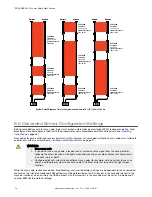
Page 70: ...o the procedure for non cascadeable emitters and receivers see Operating Instructions on page 48 Scan codes for each emitter and receiver pair must match However for cascaded installations scan codes must alternate on adjacent systems as described in Installation of Multiple Systems on page 27 WARNING Use a scan code If you do not use a scan code a receiver can synchronize to the signal from the w...

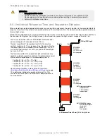
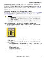
Page 71: ...ht screen function Perform the following procedure only on the first receiver in the cascade closest to the machine interface 1 From either normal operation or a power OFF condition set the second and fifth DIP switches RR and T L both to the left RR and T position 2 Set the third and fourth DIP switches the second T L and RR both to the right L and OFF position The first and sixth DIP switches ar...

Page 72: ...r s display flashes If simultaneity is not met on opening the closed contact can be opened later after more than 3 seconds then both contacts must be closed again bn wh bu bk E stop 1 E stop 2 E stop N 22 awg Figure 29 Wiring of emergency stop buttons to the last receiver in the cascade QDE2R4 8 D Cable Pinout 16 Pin Color Description 1 brown bn Ch 1a 2 black bk Ch 1b 3 blue bu Ch 2b 4 no connecti...

Page 73: ...ed and the EZ SCREEN light curtain reset if using latch mode This allows the monitoring circuits to check each switch and its wiring to detect faults Failure to test each switch individually in this manner could result in undetected faults and create an unsafe condition which could result in serious bodily injury or death WARNING Reset Routine Required Allowing the machine to restart as soon as th...

Page 74: ... machine The safety switches and actuators used with the cascaded system must be designed and installed so that they cannot be easily defeated They must be mounted securely so that their physical position cannot shift using reliable fasteners that require a tool to remove Mounting slots in the housings are for initial adjustment only final mounting holes must be used for permanent location 8 8 2 P...

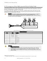
Page 75: ...ies of interlocking safety switches is monitored by the EZ SCREEN the failure of one switch in the system may be masked or not detected at all bn wh bu bk 22 awg Open Open Open Figure 31 Monitoring positive opening safety switches on multiple gates QDE2R4 8 D Cable Pinout 18 Pin Color Description 1 brown bn Ch 1a 2 black bk Ch 1b 3 blue bu Ch 2b 4 no connection 5 no connection 6 no connection 7 no...

Page 76: ...ils may result in an unsafe condition i e the accumulation of faults results in the loss of the safety function Non detection of a failure If a good guard is opened the EZ SCREEN de energizes its outputs a normal response But if a faulty guard is then opened and closed before the good guard is re closed the failure on the faulty guard is not detected This system also is no longer redundant and may...

Page 77: ...or down wait a second or two then power it up Note If the receiver is set for latch output a manual reset using a remote switch as described in Reset Procedures on page 50 is required to resume full operation Emitter Reset Power the sensor down wait a second or two and then power it up WARNING Lockouts and power failures indicate a problem Attempts to continue to operate machinery by bypassing the...

Page 78: ...EDM Input on page 40 If the error continues remove power to the guarded machine disconnect the OSSD loads disconnect the EDM input signals configure EDM for No Monitoring see Machine Primary Control Elements and EDM Input on page 40 and conduct the Initial Checkout procedure in Initial Checkout Procedure on page 32 If the error clears the problem is in the external device contacts or wiring or is ...

Page 79: ... Error This error occurs when beam s that have been blanked programmed to ignore a fixed object become clear when the object is removed or moved Reposition the object and perform a key reset or cycle power Re program teach the fixed blanked object s see Fixed Blanking on page 35 Programming Timeout Error This error occurs when the Fixed Blanking programming mode teach exceeds the ten minute limit ...

Page 80: ...occurs the receiver Reset indicator is amber all Zone indicators will be red and the system Status LED will be red The 3 digit display shows a numerical value equal to one less than the total number of beams For example if an array has 50 beams total the display would show 49 and the emitter s Status indicator flashes green See Status Indicators on page 51 and Troubleshooting on page 77 On a 10 be...

Page 81: ...r the lens of the BT 1 with electrical tape to block optical light from entering the receiver lens 3 Press the RCV button on the BT 1 and position the Beam Tracker on the wires going to the EZ SCREEN or any other nearby wires 4 Install proper transient suppression across the load to reduce the noise 9 4 2 Check for Sources of Optical Noise 1 Turn off the emitter completely block the emitter or ope...

Page 82: ...Engineering Corporate headquarters is located at 9714 Tenth Avenue North Minneapolis MN 55441 USA Website www bannerengineering com Phone 1 888 373 6767 For worldwide locations and local representatives visit www bannerengineering com 10 6 Banner Engineering Corp Limited Warranty Banner Engineering Corp warrants its products to be free from defects in material and workmanship for one year followin...

Page 83: ...t intended for such purposes will void the product warranty Any modifications to this product without prior express approval by Banner Engineering Corp will void the product warranties All specifications published in this document are subject to change Banner reserves the right to modify product specifications or update documentation at any time Specifications and product information in English su...

Page 84: ...nd shock of 10 g for 16 milliseconds 6 000 cycles Mounting Hardware Emitter and receiver each are supplied with a pair of swivel end mounting brackets Models 1050 mm and longer also include a swivel center mount bracket Mounting brackets are 8 gauge cold rolled steel black zinc finish Cables and Connections See Accessories on page 88 Certifications 11 2 Emitter Specifications Supply Voltage at the...

Page 85: ... with total number of sensing beams and whether Sync beam is blocked Model Beam 1 Sync Beam All Other Beams 14 mm 109 ms to 800 ms 33 ms to 220 ms 25 mm 81 ms to 495 ms 25 ms to 152 ms Reset Input Reset input must be high for 0 25 to 2 seconds and then low to reset the receiver High Signal 10 to 30 V dc at 30 mA typical Low Signal 0 to 3 V dc Closed Switch Time 0 25 to 2 seconds Controls and Adjus...

Page 86: ...12N for ESD model emitters and receivers 20 mm 0 79 20 mm 0 79 Ø 60 mm 20 mm 0 79 17 5 mm 0 69 55 mm 2 17 50 mm 1 97 4 2 mm 0 17 55 6 mm 2 19 15 mm 0 59 20 0 mm 0 79 10 mm 0 39 9 5 mm 0 37 36 mm 1 42 Ø 8 3 mm 0 33 Ø 7 mm 0 28 11 6 Emitter and Receiver Mounting Dimensions and Location of Defined Area EZ SCREEN 14 30 mm Safety Light Screen 86 www bannerengineering com Tel 1 888 373 6767 ...

Page 87: ...35 4 in SLS 1050 1120 mm 44 1 in 1153 mm 45 4 in 1095 mm 43 1 in 1050 mm 41 3 in SLS 1200 1270 mm 50 0 in 1303 mm 51 3 in 1245 mm 49 0 in 1200 mm 47 2 in SLS 1350 1420 mm 55 9 in 1453 mm 57 2 in 1395 mm 54 9 in 1350 mm 53 1 in SLS 1500 1569 mm 61 8 in 1602 mm 63 1 in 1544 mm 60 8 in 1500 mm 59 1 in SLS 1650 1719 mm 67 7 in 1752 mm 69 0 in 1694 mm 66 7 in 1650 mm 65 0 in SLS 1800 1869 mm 73 6 in 19...

Page 88: ...XS SC26 2 Non Expandable Models Expandable Models Description SC26 2 XS26 2 26 convertible I O and 2 Redundant Solid State Safety Outputs SC26 2d XS26 2d 26 convertible I O and 2 Redundant Solid State Safety Outputs with Display SC26 2e XS26 2e 26 convertible I O and 2 Redundant Solid State Safety Outputs with Ethernet SC26 2de XS26 2de 26 convertible I O and 2 Redundant Solid State Safety Outputs...

Page 89: ... style QD 5 Pin Mini style QD 12 6 Remote Reset Switch Model Description EZA RR 1 External normally open reset switch with 8 pin M12 Euro style quick disconnect fitting can be interconnected using cordset models QDE 8 D DEE2R 8 D or CSB M1281 12 7 Lens Shields Adhesive Backed Model21 Snap On Model22 Sensor Defined Area23 EZS 150 EZSS 150 150 mm 5 9 in EZS 300 EZSS 300 300 mm 11 8 in EZS 450 EZSS 4...

Page 90: ...e included Available without a base by adding the suffix NB to the model number for example MSA S42 1NB Stand Model Pole Height Useable Stand Height Overall Stand Height MSA S24 1 610 mm 24 in 483 mm 19 in 616 mm 24 25 in MSA S42 1 1067 mm 42 in 940 mm 37 in 1073 mm 42 25 in MSA S66 1 1676 mm 66 in 1550 mm 61 in 1682 mm 66 25 in MSA S84 1 2134 mm 84 in 2007 mm 79 in 2140 mm 84 25 in MSA S105 1 266...

Page 91: ... 26 in 716 mm 28 2 in 686 mm 27 in MSM32A 750 mm 29 5 in 864 mm 34 in 919 mm 36 2 in 889 mm 35 in MSM36A 900 mm 35 4 in 965 mm 38 in 1021 mm 40 2 in 991 mm 39 in MSM44A 1050 mm 41 3 in 1168 mm 46 in 1224 mm 48 2 in 1194 mm 47 in MSM48A 1200 mm 47 2 in 1270 mm 50 in 1326 mm 52 2 in 1295 mm 51 in 12 11 SSM Series Corner Mirrors Robust for heavy duty applications Extra wide for use with long range op...

Page 92: ... 1661 mm 65 4 in 1628 mm 64 1 in SSM 1750 1650 mm 65 0 in 1750 mm 68 9 in 1861 mm 73 3 in 1828 mm 72 0 in SSM 1900 1800 mm 70 9 in 1900 mm 74 8 in 2011 mm 79 2 in 1978 mm 77 9 in 12 12 Mounting Brackets See Replacement Parts on page 17 for standard brackets Contact Banner Engineering for more information Order one EZA MBK bracket per sensor two per pair EZA MBK 2 Adapter bracket for mounting SSM s...

Page 93: ...g bracket system for L configuration of two cascaded EZ SCREEN light screens M5 and M6 mounting hardware 12 13 Alignment Aids Model Description LAT 1 SS Self contained visible beam laser tool for aligning any EZ SCREEN 14 mm and 30 mm emitter receiver pair Includes retroreflective target material and mounting clip EZA LAT SS Replacement adaptor clip hardware for SLS models EZA LAT 2 Clip on retror...

Page 94: ...sulated IP67 T30RGX8PQ8 K30LRGX8PQ8 Polycarbonate housing 30 mm thermoplastic dome 22 mm base mount Fully encapsulated IP67 K50LRGX8PQ8 Polycarbonate housing 50 mm thermoplastic dome 30 mm base mount Fully encapsulated IP67 K80LRGX8PQ8 Polycarbonate housing 50 mm thermoplastic dome flat or DIN mount Encapsulated electronics IP67 26 Available in a kit that includes one M18 EZ LIGHT one SMB18A mount...

Page 95: ...for Conformité Européenne French translation of European Conformity The CE mark on a product or machine establishes its compliance with all relevant European Union EU Directives and the associated safety standards Clutch A mechanism that when engaged transmits torque to impart motion from a driving member to a driven member Control Reliability A method of ensuring the performance integrity of a co...

Page 96: ... safety outputs for example Final Switching Devices to trip or latch If any fixed objects are moved within or removed from the defined area a Lockout condition results Floating Blanking See Reduced Resolution FMEA Failure Mode and Effects Analysis A testing procedure by which potential failure modes in a system are analyzed to determine their results or effects on the system Component failure mode...

Page 97: ...s the machine s normal operating motion in such a way that the element is last in time to operate when machine motion is either initiated or arrested Machine Response Time The time between the activation of a machine stopping device and the instant when the dangerous parts of the machine reach a safe state by being brought to rest Minimum Object Sensitivity MOS The minimum diameter object that a s...

Page 98: ... mode is used when the part is both inserted to begin the operation and removed after the operation by the operator PSDI is commonly confused with Trip Initiate PSDI is defined in OSHA CFR1910 217 Banner safety light screen systems may not be used as PSDI devices on mechanical power presses per OSHA regulation 29 CFR 1910 217 Q Qualified Person A person who by possession of a recognized degree or ...

Page 99: ...ntal Guarding Additional safeguarding device s or hard guarding used to prevent a person from reaching over under through or around the primary safeguard or otherwise accessing the guarded hazard T Test Piece An opaque object of sufficient size used to block a light beam to test the operation of a safety light screen system Auto Start Restart Trip Condition The safety outputs of a safety light scr...

Page 100: ...or 52 External Device Monitoring EDM 10 F Final Switching Device FSD 8 I indicator Emitter Power Fault 52 initial power up 32 M Machine Primary Control Elements MPCEs 8 O Output Signal Switching Device OSSD 8 S suitable applications 10 T Trip or Latch Output 10 trip latch output 50 ...

Reviews: