11.3 Receiver Specifications
Supply Voltage at the Device
24 V dc ±15% (use a SELV-rated power supply according to EN IEC
60950). The external voltage supply must be capable of buffering brief
mains interruptions of 20 ms, as specified in IEC/EN 60204-1.
Residual Ripple
±10% maximum
Supply Current (no load)
275 mA maximum, exclusive of OSSD1 and OSSD2 loads (up to additional
0.5 A each)
Response Time
Dependent on the number of sensing beams; see the models table for the
number of beams and response time.
CSSI Response Time (SLSC.. cascade models only)
Response time for a cascade receiver due to opening contacts at the
cascade interface (CSSI): 40 ms max (contacts must open for 60 ms
minimum).
Output Signal Switching Devices (OSSDs)
Two redundant solid-state 24 V dc, 0.5 A max. sourcing OSSD
(Output Signal Switching Device) safety outputs. (Use optional
interface modules for ac or larger dc loads.) Capable of the Banner
"Safety Handshake".
ON-State voltage: ≥ Vin-1.5 V dc
OFF-State voltage: 1.2 V dc max. (0 to 1.2 V dc)
Maximum load capacitance: 1.0 µF
Minimum load inductance: 10 H
Leakage current: 0.50 mA maximum
Cable resistance: 10 Ω max.
OSSD test pulse width: 100 to 300 microseconds typical
OSSD test pulse period: 10 ms to 27 ms (varies with number of
beams)
Switching current: 0 to 0.5 A
Auxiliary Output Switching Capacity
Current-sourcing (PNP) solid-state output, 24 V dc at 75 mA max.
EDM Input
+24 V dc signals from external device contacts can be monitored (one-
channel, two-channel, or no monitoring) via EDM1 terminal in the receiver.
High Signal: 10 to 30 V dc at 30 mA typical
Low Signal: 0 to 3 V dc
Dropout Time: 200 ms max.
Recovery Time
Blocked to Clear (OSSDs turn On; varies with total number of sensing
beams and whether Sync beam is blocked):
Model
Beam 1 (Sync Beam)
All Other Beams
14 mm
109 ms to 800 ms
33 ms to 220 ms
25 mm
81 ms to 495 ms
25 ms to 152 ms
Reset Input
Reset input must be high for 0.25 to 2 seconds and then low to reset the
receiver
High Signal: 10 to 30 V dc at 30 mA typical
Low Signal: 0 to 3 V dc
Closed Switch Time: 0.25 to 2 seconds
Controls and Adjustments
Scan Code selection: 2-position switch (code 1 or 2). Factory default
position is code 1
Trip/Latch Output selection: Redundant switches. Factory default
position is T (trip).
EDM/MPCE Monitor selection: 2-position switch selects between 1-
or 2-channel monitoring. Factory default position is 2-channel
monitoring.
Reduced Resolution: Redundant switches. Factory default position is
Off.
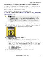
Status Indicators
Amber Reset Indicator: indicates whether the System is ready for
operation or requires a reset
Bi-color (red/green) Status indicator: indicates general system and
output status
Bi-color (red/green) Zone Status indicators: indicate condition (clear
or blocked beam) of a defined group of beams
7-Segment Diagnostic indicator (3 digits): indicates proper operation,
scan code, error code, or total number of blocked beams
Ambient Light Immunity
10,000 lux at 5° angle of incidence
Strobe Light Immunity
Totally immune to one Federal Signal Corp. "Fireball" model FB2PST
strobe
11.4 End Cap Brackets
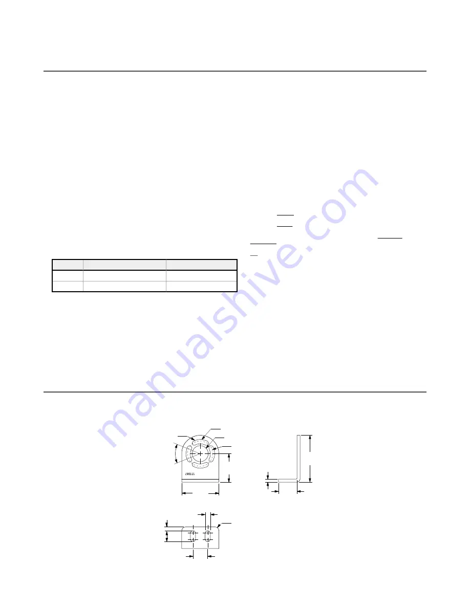
Model EZA-MBK-11: End cap brackets are included for emitter or receiver. Dimensions are identical for stainless steel
model EZA-MBK-11N for ESD model emitters and receivers.
50 mm
(1.96")
25 mm
(0.98")
4.2 mm
(0.17")
63.2 mm
(2.49")
Ø 21.5 mm
(0.85")
4 x 5.8 mm (0.23")
wide slots
4 x R 19.4 mm
(0.76")
38.2 mm
(1.50")
Ø 33 mm
(1.30")
4 x 45
20 mm
(0.79")
2 x R 5 mm
(0.20")
2 x 5 mm
(0.20")
2 x 15 mm
(0.59")
2 x 7 mm
(0.28")
EZ-SCREEN
®
14/30 mm Safety Light Screen
www.bannerengineering.com - Tel: + 1 888 373 6767
85

