9 Industrial Ethernet Overview
9.1 Device Setup
9.1.1 Set IP Address
When shipped, the device is assigned a default IP address - 192.168.0.1, a default Subnet Mask - 255.255.255.0, and a
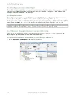
default gateway - 0.0.0.0. To change these defaults, click on Main Menu > System > Communications > Ethernet
I/O.
9.1.2 Set Industrial Ethernet Protocol (EIP/Modbus/TCP/PCCC/PROFINET
®
)
The Industrial Ethernet communication channel is disabled by default. In order to enable this channel, click on Main Menu
> System > Communications > Industrial Ethernet > Connection. Select the channel of interest (EIP, Modbus/TCP,
PROFINET, or PCCC). Only one type of connection can be established at any given time.
Information about an established connection can be obtained from Main Menu > System > Communications >
Industrial Ethernet > Status screen. Click on the connection of interest to view details.
This device provides extensive logging for the communication that occurs over the Industrial Ethernet connection. Logs can
either be viewed from Main Menu > System > Communications > Industrial Ethernet > View Logs, or Main Menu
> Logs > Communication Logs > Industrial Ethernet.
9.1.3 Set Trigger Mode
The sensor can be triggered using either the hardware trigger or through over the Industrial EtherNet. In order to only
accept triggers generated through the Industrial EtherNet communication channel, click on the Main Menu > Imager >
Trigger, and select Industrial EtherNet Only from the drop-down menu.
9.2 Supported Functions
The iVu Plus Series sensor is controlled over EtherNet/IP and Modbus/TCP using the input and output data it makes
available as a slave device for those protocols.
Here are some of the Sensor operations that can be performed using input and output values:
•
Product Change
•
Teach Enable
•
Trigger the sensor
•
Read output indicators (pass/fail/ready/error)
•
Read counters (pass, fail, system error, missed trigger, frame count, iteration count)
•
Read iVu sensor results
•
On Barcode, change compare string and its mask
9.2.1 iVu Input Values
The operation of the iVu Plus Series sensor can be controlled through input bits and commands.
Register/Input Coil Bits
The following commands can only be executed using bits:
Input Coil Bit
Command
Description
0
Product Change
Execute a product change (inspection number specified in the "Product Change
Number" 32-bit integer register).
1
Teach Latch
Latch a teach flag. Teach is executed on next trigger.
2
Trigger
Causes system to trigger an inspection if ready.
3
Gated Trigger
Causes system to start looking for requested barcodes (BCR products only)
5
Set BCR String
Sets barcode compare string (BCR products only)
6
Set BCR Mask
Sets masks for barcode compare string (BCR products only)
15
Command
Set this bit to 1 to execute the command entered in the Command ID Register.
iVu Plus TG Gen2 Image Sensor
www.bannerengineering.com - Tel: 763.544.3164
107


