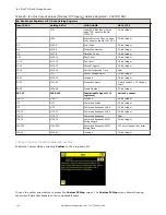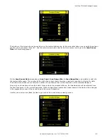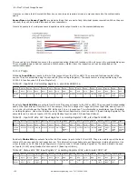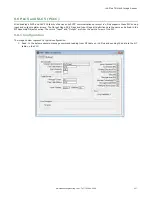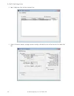
8. Click on S2 to go to the configuration window and add a submodule .
9. Click on the Drop-Down Arrow next to Disabled to open the list of submodule slots.
10. Select a submodule and hit enter.
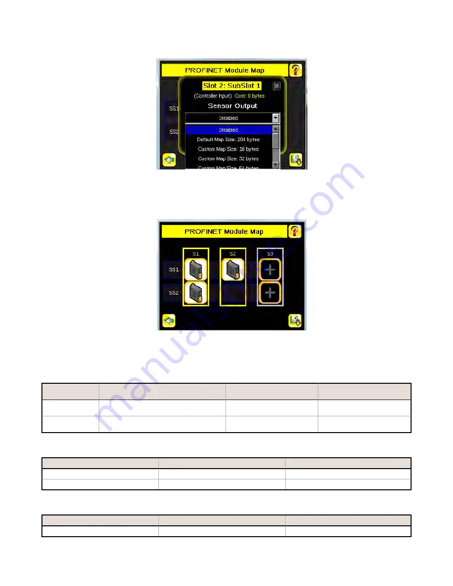
The submodule slot now shows an icon, which means that it has been configured.
11. Set up all submodules for your application.
The iVu Plus PROFINET configuration is complete. The PLC can be configured to complete the PROFINET connection.
Description of Modules
Table 40: Assignment of Slots and Subslots
Slot 1 - TG Control and Status Module
Slot 2 - TG Sensor Output
Module
Slot 3 - Command Channel
Module
Subslot 1
TG Inspection Result Submodule
sensor output submodules
Command Channel Command
submodules
Subslot 2
TG Device Control Submodule
—
Command Channel Response
submodules
Table 41: TG Control and Status Module (Ident 0x00000010)
Number of Physical Subslots
Subslot Label
Subslot Number
1
1.1 TG Inspection Result Submodule
1 (0x1)
1
1.2 TG Device Control Submodule
2 (0x2)
Table 42: TG Sensor Output Module (Ident 0x00000040)
Number of Physical Subslots
Subslot Label
Subslot Number
1
2.1 sensor output submodules
1 (0x1)
iVu Plus TG Gen2 Image Sensor
148
www.bannerengineering.com - Tel: 763.544.3164

