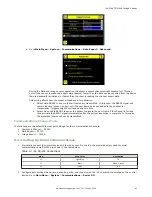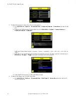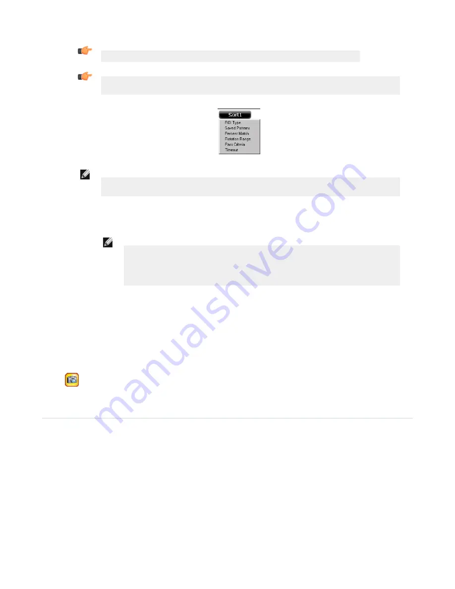
Tip: Use the short-cut menu in the upper-right of the screen to select an ROI-type.
Tip: For better results, make sure that the ROI bounds the image of the pattern as tightly as
possible.
NOTE: When running a Sort inspection, the sensor will look for any possible patterns to match
anywhere within the field of view.
•
The Percent Match setting adjusts how closely the inspected part or label needs to match any of the ten
stored patterns. The Percent Match scale is from 0 to 100, where 0 is the most tolerant and 100 is the least
tolerant. Move the slider to the left or to the right to adjust the setting. For the best results, use a value
from 50 to 90.
NOTE: When running a Sort inspection, the sensor will highlight in green any pattern
matches that are within the specified Rotation Range and meet or exceed the value
specified for Percent Match. Patterns that are within the specified Rotation Range and
within approximately 20% below the specified value for Percent Match will be colored
yellow.
•
The Rotation Range sets the expected rotation of parts or labels during an inspection. For example, a
value of 45 means that the part may rotate 45 degrees in either direction from the reference part and still
pass. Move the slider from 0 to 180 degrees. Note that the smaller the rotation range, the faster the
inspection will run.
4. Repeat these steps for subsequent patterns and store each pattern in an empty pattern storage slot.
5. Set the Pass Criteria (assuming only two stored patterns):
•
Any Saved Pattern—Pass condition if the sensor matches either Pattern_1, Pattern_2, or both
•
All Saved Patterns—Pass condition if the sensor matches both Pattern_1 AND Pattern_2
•
Single Saved Pattern—Pass condition if the sensor matches either Pattern_1 OR Pattern_2, but NOT both
•
Specific Save Pattern (Must also select the saved pattern to match, for example, select Pattern_2)—Pass
condition any time the sensor matches Pattern_2
6.
Use the Manual Trigger, located in the lower-right corner of the screen, to test good and bad parts. Adjust
settings as necessary and retest.
7.6 Configuring Motion
Main Menu > Inspection > Motion
This Motion menu shows up when Motion is Enabled under the Inspection Properties menu. Enable Motion when the part is
expected to move or rotate. Motion settings involve selecting the number of edges to locate, adjusting sensitivity, and
selecting whether or not rotation is enabled. These settings appear on the Inspection Menu after Motion is set to 'Enabled'.
Motion is enabled only when Area and/or Blemish sensors are included in the inspection.
iVu Plus TG Gen2 Image Sensor
72
www.bannerengineering.com - Tel: 763.544.3164


