background image

Introduction

The iVu TG Image Sensor is used to monitor labels, parts, and packaging for type, size, orientation, shape, and location. The sensor has
an integrated color touch screen display making installation, setup and configuration easy without requiring a PC.


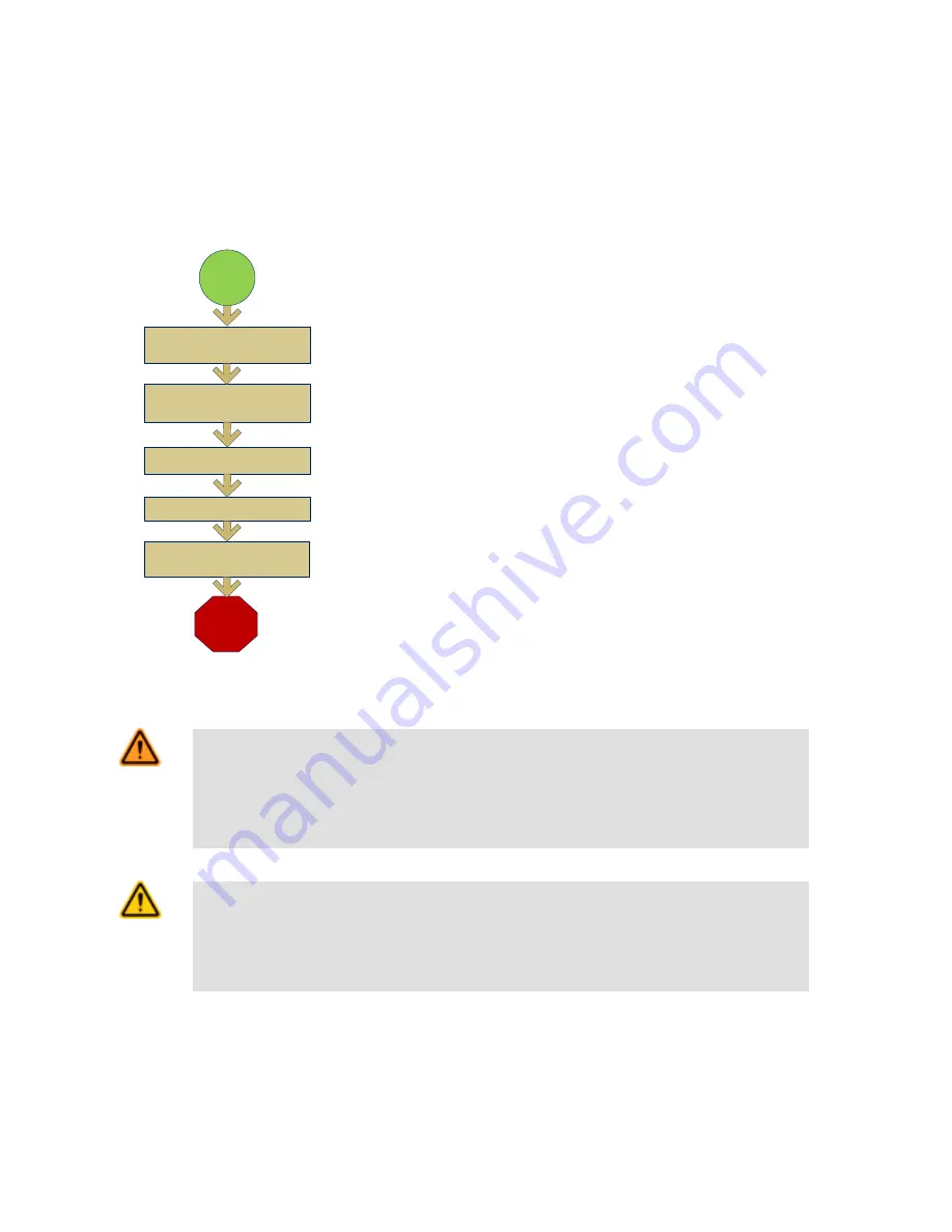
Finish

Set Sensor Parameters

Start

Install and Connect the 

Sensor

Initial Boot into Demo Mode

Select Sensor Type

Acquire A Good Image


Quick Start Overview

This guide is designed to provide the necessary information to get the iVu TG sensor
up and running quickly. It provides an overview of the sensor and illustrates how to set
up the sensor to inspect a label, part, or packaging. The flow chart at left provides an
overview of the process.

Related Information

The following documentation is available on the Product CD:

• Datasheets:

• iVu TG Datasheet
• iVu TG Remote Display
• iVu Series Remote Display Datasheet

• Other:

• iVu TG Sensor Reference
• iVu TG Communications Guide
• iVu TG User's Manual

In addition, there is integrated Help built into the sensor itself.

WARNING: Not To Be Used for Personnel Protection

Never use this product as a sensing device for personnel protection. Doing so could lead to seri-
ous injury or death.
 This product does NOT include the self-checking redundant circuitry necessary to
allow its use in personnel safety applications. A sensor failure or malfunction can cause either an ener-
gized or de-energized sensor output condition.

CAUTION: Electrostatic Discharge

Avoid the damage that electrostatic discharge (ESD) can cause to the Sensor.

Always use a proven method for preventing electrostatic discharge when installing a lens or attaching a
cable.

Rev. C

www.bannerengineering.com - tel: 763-544-3164

3

Summary of Contents for iVu TG

Page 1: ...iVu TG Quick Start Guide Rev C 10 3 2011 143367...

Page 2: ...with Integrated Display 5 Cable Connections for the iVu TG with a Remote Display 5 Demo Mode 7 Sensor Types 7 Selecting a Sensor Type 7 Acquiring a Good Image 8 Configuring an Area Sensor 11 Configur...

Page 3: ...entation is available on the Product CD Datasheets iVu TG Datasheet iVu TG Remote Display iVu Series Remote Display Datasheet Other iVu TG Sensor Reference iVu TG Communications Guide iVu TG User s Ma...

Page 4: ...allow the sensor to be mounted either perpendicular to the part or at an adjustable angle Available iVu Brackets SMBIVURAL SMBIVURAR SMBIVUU Thread three M4 x 4mm screws through the bracket into the m...

Page 5: ...een Output 2 Output NOTE Microlens models show C Mount model connections are identical Cable Connections for the iVu TG with a Remote Display The cable connections on the iVu sensor are shown below an...

Page 6: ...External Trigger Input 5 Gray Remote Teach Input 1 White Output 1 Output 8 Red Ready Output 4 Yellow Strobe Out 5V dc only Output 3 Green Output 2 Output 9 Orange Not used N A 10 Light Blue Not used N...

Page 7: ...s normal operating mode with default settings NOTE You may return to Demo Mode any time by going to Main Menu System Sensor Type and select ing Demo Mode Sensor Types The iVu TG sensor includes three...

Page 8: ...background Depending on the target this may mean the integral ring light is not the best choice and other Banner lights should be consid ered Adjust the mounting angle to provide the clearest image o...

Page 9: ...il the Focus Number peaks NOTE Turning the Focusing Window counter clockwise focuses on closer objects while turning the Focusing Window clockwise focuses on more distant objects 3 Once the best image...

Page 10: ...the focus until the Focus Number peaks 3 Replace the Lens Enclosure on the camera C Mount Models D C A B E C A C Mount Lens B Lens Enclosure C Retainer Ring optional D Filter optional E Filter Retain...

Page 11: ...ok for To set the Intensity Range use the eye dropper on the left of the screen to select the target feature then use the slider bar at the bottom of the display to fine tune the selection As the slid...

Page 12: ...ges within the ROI The Sensitivity value helps account for light varia tions that might affect how well the sensor detects edges The Sensitivity scale is from 0 to 100 where 0 means least sensitive an...

Page 13: ...he reference part or label The Percent Match scale is from 0 to 100 where 0 is the most tolerant and 100 is the least tolerant Move the slider to the left or to the right to adjust the setting For the...

Page 14: ...ary edge and the second edge moves and rotates in relation to this primary edge The primary edge is identified by a small O as shown below Sensitivity is used to fine tune how accurately the sensor de...

Reviews: