background image

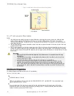
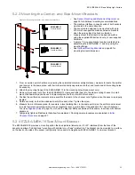
European Application example: Model SLLVP23-630

S = (1600 × 0.3325) + 72 = 604 mm

Mount the EZ-SCREEN LS Basic emitter and receiver so that no part of the defined area will be closer than 604 mm to the

closest reachable hazard point on the guarded machine.

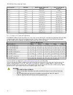
5.1.3 Reducing or Eliminating Pass-Through Hazards

pass-through

 hazard is associated with applications where personnel may pass through a safeguard, such as the EZ-

SCREEN LS Basic Safety Light Curtain (which issues a stop command to remove the hazard), and then continues into the

guarded area. This is common in access and perimeter guarding applications. Subsequently, their presence is no longer

detected, and the related danger becomes the unexpected start or restart of the machine while personnel are within the

guarded area.
A pass-through hazard typically results from large safety distances calculated from long stopping times, large minimum

object sensitivities, reach-over, reach-through, or other installation considerations. A pass-through hazard can be generated

with as little as 75 mm (3 in) between the sensing field and the machine frame or hard (fixed) guarding.
Eliminate or reduce pass-through hazards whenever possible. While it is recommended to eliminate the pass-through hazard

altogether, this may not be possible due to machine layout, machine capabilities, or other application considerations.
One solution is to ensure that personnel are continually sensed while within the hazardous area. This can be accomplished

by using supplemental safeguarding, such as described by the safety requirements in ANSI B11.19 or other appropriate

standards.
An alternative method is to ensure that once the safeguarding device is tripped it will latch and will require a deliberate

manual action to reset. This method of safeguarding relies upon the location of the reset switch as well as safe work

practices and procedures to prevent an unexpected start or restart of the guarded machine.

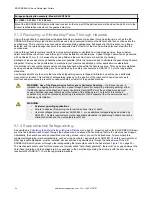
WARNING: Use of the Banner device for Access or Perimeter Guarding

— If a Banner device is

installed in an application that results in a pass-through hazard (for example, perimeter guarding), either

the Banner device or the Machine Primary Control Elements (MPCEs) of the guarded machine must

cause a Latched response following an interruption of the defined area. The reset of this Latched

condition may only be achieved by actuating a reset switch that is separate from the normal means of

machine cycle initiation.

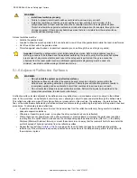
WARNING:

Perimeter guarding applications

Failure to observe this warning could result in serious injury or death.

Use lockout/tagout procedures per ANSI Z244.1, or use additional safeguarding as described by
ANSI B11.19 safety requirements or other applicable standards if a passthrough hazard cannot be
eliminated or reduced to an acceptable level of risk.

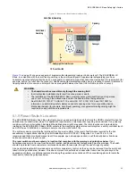
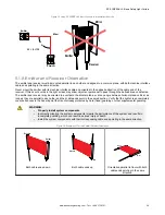
5.1.4 Supplemental Safeguarding

As described in 

Calculating the Safety Distance (Minimum Distance)

 on page 21, properly position the EZ-SCREEN LS Basic

such that an individual cannot reach through the defined area and access the hazard point before the machine has stopped.
Additionally, the hazard cannot be accessible by reaching around, under, or over the defined area. To accomplish this,

supplemental guarding (mechanical barriers, such as screens or bars), as described by ANSI B11.19 safety requirements or

other appropriate standards, must be installed. Access will then be possible only through the defined area of the EZ-

SCREEN LS Basic System or through other safeguarding that prevents access to the hazard (see 

Figure 13 

on page 25).

The mechanical barriers used for this purpose are typically called "hard (fixed) guarding"; there must be no gaps between the

hard (fixed) guarding and the defined area. Any openings in the hard (fixed) guarding must comply with the safe opening

requirements of ANSI B11.19 or other appropriate standard.

EZ-SCREEN

®

 LS Basic Safety Light Curtain


24

www.bannerengineering.com - Tel: + 1 888 373 6767


Summary of Contents for LS Basic

Page 1: ...EZ SCREEN LS Basic Safety Light Curtain Instruction Manual Original Instructions 204120 Rev G 31 October 2022 Banner Engineering Corp All rights reserved 204120...

Page 2: ...Distance 21 5 1 2 Formula and Examples 22 5 1 3 Reducing or Eliminating Pass Through Hazards 24 5 1 4 Supplemental Safeguarding 24 5 1 5 Reset Switch Location 25 5 1 6 Adjacent Reflective Surfaces 26...

Page 3: ...ecovery Procedures 58 9 2 1 Receiver Error Codes 59 9 2 2 Emitter Error Codes 60 9 3 Electrical and Optical Noise 60 9 3 1 Check for Sources of Electrical Noise 60 9 3 2 Check for Sources of Optical N...

Page 4: ...tem including input devices control systems and output devices is properly configured and installed operational and working as intended for the application Periodically re verify as needed that the en...

Page 5: ...ve in UK Tony Coghlan Managing Director Turck Banner LTD Blenheim House Blenheim Court Wickford Essex SS11 8YT Great Britain EZ SCREEN LS Basic Safety Light Curtain www bannerengineering com Tel 1 888...

Page 6: ...Safeguarding ANSI B11 20 Manufacturing Systems ANSI B11 21 Machine Tools Using Lasers ANSI B11 22 Numerically Controlled Turning Machines ANSI B11 23 Machining Centers ANSI B11 24 Transfer Machines AN...

Page 7: ...itchgear General Rules IEC 60947 5 1 Low Voltage Switchgear Electromechanical Control Circuit Devices IEC 60947 5 5 Low Voltage Switchgear Electrical Emergency Stop Device with Mechanical Latching Fun...

Page 8: ...remely high degree of confidence that when properly installed no system component even if it should ever fail can cause a failure to danger Because of the dual scan technology EZ SCREEN LS Basic senso...

Page 9: ...signal is issued at any point in the machine s stroke or cycle such as part revolution clutched machines Under no circumstances may the EZ SCREEN LS Basic be used on full revolution clutched machinery...

Page 10: ...set procedure The Diagnostic Display is used to diagnose causes of a Lockout condition See Troubleshooting on page 58 3 2 Models An EZ SCREEN LS Basic Safety Light Curtain System refers to a compatibl...

Page 11: ...nd Receiver 23 mm 350 350 mm 420 420 mm 630 630 mm 910 910 mm 1050 1050 mm 1190 1190 mm 1260 1260 mm 1330 1330 mm 1540 1540 mm 1820 1820 mm Blank no pigtail RD connection Example SLLVP23 350 To determ...

Page 12: ...ll beams are clear The Trip Output also automatically resets after all beams are cleared WARNING Use of automatic trip or manual latch start restart Failure to follow these instructions could result i...

Page 13: ...gtail cable with a 5 pin M12 male quick disconnect QD DELSE 51D An 8 wire flying lead RD cordset RDLS 8 D Each connection option is intended for maximum flexibility to solve unique application require...

Page 14: ...er s OSSD output status Figure 5 EZ SCREEN LS with M18 EZ LIGHT 3 3 7 Status Indicators Status indicators on both the emitter and receiver are visible on each sensor s front panel Emitter Bi color red...

Page 15: ...total number of blocked beams Bi color red green Alignment indicators show status of a group of beams 35 mm of indicator along the length of the exit window aligned and clear green ON or blocked and...

Page 16: ...Class III per IEC 61140 1997 Environmental Rating IP65 IP67 Operating Conditions 20 C to 55 C 4 F to 131 F 95 maximum relative humidity non condensing Mounting Hardware All mounting hardware is ordere...

Page 17: ...y connecting pin 8 violet wire to 0 V DC or leaving it open not connected Select Scan Code 2 by connecting pin 8 violet wire to 24 V DC Status Indicators Amber Run Mode Indicator indicates the System...

Page 18: ...ole to Hole Length with Brackets Out L2 mm Hole to Hole Length with Brackets In L3 mm Defined Area 2 mm SLL 350 355 mm 14 0 in 397 1 339 1 350 SLL 420 425 mm 16 7 in 466 6 408 6 420 SLL 630 634 mm 25...

Page 19: ...0 1542 mm 60 7 in 1584 1 1526 1 1540 SLL 1820 1821 mm 71 7 in 1863 1 1805 1 1820 4 5 Mounting Dimensions All measurements are listed in millimeters inches unless noted otherwise See Dimensions on page...

Page 20: ...Center Mount Brackets Dimensions Figure 10 EZLSA MBK 12 Side Mount Brackets Dimensions Figure 11 EZLSA MBK 16 EZ SCREEN LS Basic Safety Light Curtain 20 www bannerengineering com Tel 1 888 373 6767...

Page 21: ...r and Receiver Orientation see Emitter and Receiver Orientation on page 29 Adjacent Reflective Surfaces see Adjacent Reflective Surfaces on page 26 Use of Corner Mirrors see Use of Corner Mirrors on p...

Page 22: ...esponse time of all devices or controls that react to stop the machine If all devices are not included the calculated safety distance Ds or S will be too short which can lead to serious injury or deat...

Page 23: ...n Applications The Minimum Distance formula for European applications S K T C S the Minimum Distance in mm from danger zone to light screen center line K hand speed constant see Note 2 below 2000 mm s...

Page 24: ...procedures to prevent an unexpected start or restart of the guarded machine WARNING Use of the Banner device for Access or Perimeter Guarding If a Banner device is installed in an application that res...

Page 25: ...matic reset that turns the OSSD outputs ON when the defined area is unobstructed clear Per application requirements a latch response requiring a manual reset to a power up condition or after an interr...

Page 26: ...oblems results in incomplete guarding and an optical short circuit that could result in serious injury or death Do not locate the defined area near a reflective surface Perform the trip test as descri...

Page 27: ...t cause a blocked condition due to an optical short circuit Alignment indicator LEDs are ON green and the OSSDs are ON For 0 1 m to 3 m 4 in to 10 ft Operating range d 0 13 m 5 in For Operating range...

Page 28: ...m 47 ft 13 1 m 43 ft EZ SCREEN LP SLP 7 m 23 ft 6 5 m 21 2 ft 6 0 m 19 5 ft 5 5 m 18 0 ft 5 1 m 16 6 ft EZ SCREEN LP Basic SLPVA 4 m 13 ft 3 7 m 12 1 ft 3 4 m 11 2 ft 3 1 ft m 10 3 ft 2 8 m 9 2 ft EZ...

Page 29: ...nd vertical as long as they are parallel to each other and their cable ends point in the same direction Verify that the light screen completely covers all access to the hazard point that is not alread...

Page 30: ...wn optical crosstalk may occur between sensor pairs whose emitter and receiver lenses are oriented in the same direction In this situation eliminate optical crosstalk by mounting these sensor pairs ex...

Page 31: ...system to use scan code 2 Perform a trip test to confirm the light curtain function 5 2 Mounting System Components 5 2 1 Mounting Hardware After addressing the mechanical layout considerations mount...

Page 32: ...a common point of reference ensuring the calculated minimum safety distance measure to position the emitter and receiver in the same plane with their midpoints directly opposite each other and locate...

Page 33: ...move the channel nuts from the EZLSA MBK 12 clamp and slide them into the side mounting channel A small piece of adhesive tape can be use to temporarily location the nuts within the channel 4 Position...

Page 34: ...he emitter and receiver are directly opposite each other Nothing is interrupting the defined area The defined area is the same distance from a common reference plane for each sensor The emitter and re...

Page 35: ...ce X at the emitter and receiver are equal Both sensors are level plumb check both the side and face Defined area is square Check diagonal measurements if possible Diagonal A Diagonal B Figure 27 For...

Page 36: ...rdsets to the sensors and route the sensor cables to the junction box electrical panel or other enclosure in which the interface module the redundant mechanically linked interposing relays FSDs or oth...

Page 37: ...9 or IEC60204 1 always connect the earth ground green yellow wire Do not operate the EZ SCREEN LS Basic without an earth ground connection Make the electrical connections in the order described in thi...

Page 38: ...nd receiver cables see Reference Wiring Diagrams on page 46 The 24 V dc brown wire and 0 V dc blue wire should be connected to a SELV rated supply and GND green yellow wire to earth ground If the inst...

Page 39: ...sensor rotates out of alignment the red Status indicator turns on As more beams are aligned the Alignment indicators turn from red to green and the number of blocked beam indicators decreases Indicat...

Page 40: ...ove the mirror Note An LAT 1 Laser Alignment Tool is very helpful by providing a visible red dot along the optical axis See Alignment Aids on page 70 Figure 28 on page 40 and Banner Safety Application...

Page 41: ...each leg of the sensing path for example emitter to mirror between mirror and receiver Figure 31 Trip Test with Corner Mirror Receiver Emitter Test Piece Mirror 6 If the EZ SCREEN LS Basic System pas...

Page 42: ...it switches such that a failure causes a loss of the safety stop command or the failure allows the safety function to be suspended overridden or defeated Connect both OSSD outputs to the machine contr...

Page 43: ...control system failures can occur that would result in a loss of the safety function such as a short circuit to a secondary source of energy or voltage For this reason single channel control interfaci...

Page 44: ...EDM Don t Care Don t Care Don t Care Don t Care 250 ms Max 250 ms Max 250 ms Max External Device Monitoring Wiring If not connected previously it is again strongly recommended that one normally closed...

Page 45: ...ing for System Operation After the initial trip test has been accomplished and the OSSD safety outputs and EDM connections have been made to the machine to be controlled the EZ SCREEN LS Basic is read...

Page 46: ...ound must be provided via the mounting brackets 6 5 1 Generic Wiring Diagram 5 pin and 8 pin Emitter Figure 35 Generic Wiring Diagram Emitter 24 VDC n c n c 0 VDC Bn Pin 1 Gn Ye 5 Bu 3 Bk 4 Wh 2 Emitt...

Page 47: ...yle face view MSC1 MSC3 MSC2 MSC Monitor Contacts or Jumper S33 S34 A2 S21 UM FA A S11 S22 S12 13 14 DIP Switch Configuration 1 2 ON MSC1 K1A K2A L2 23 24 MSC2 K1B K2B 33 34 MSC3 K1C K2C L1 Machine Co...

Page 48: ...pressors See WARNING Note See UM FA A module datasheet p n 141249 for complete installation instructions WARNING Properly install arc or transient suppressors Failure to follow these instructions coul...

Page 49: ...Wh 2 FSD2 FSD1 IN1 24Vdc XS SC26 2xx XS2so or XS4so 0Vdc SO1 not split SO1a SO1b EDM IN2 24Vdc 0Vdc Dual Channel Safety Stop Circuit Single Channel Safety Stop Circuit 5 pin male Euro style face view...

Page 50: ...it 1 Brown 7 Green Yellow 6 Blue 5 Black 4 White 8 Violet 3 Orange 2 Orange Black 24 V DC Scan Code Ground 0 V DC OSSD1 OSSD2 EDM Fault Output 8 pin male M12 IN1 IN2 Scan Code 1 Not connected or conne...

Page 51: ...und 0 V DC OSSD1 OSSD2 Scan Code EDM Fault Out FSD2 FSD1 Single Channel Safety Stop Circuit Dual Channel Safety Stop Circuit NOTE Do not exceed OSSD maximum load capacitance specification Scan Code 1...

Page 52: ...ult Out Not connected or connect indicator 70 mA maximum to 0 V DC as shown Other interfacing modules and solutions available See the Banner Engineering catalog or website for more information Note Se...

Page 53: ...stic Display indicates a specific error code when the emitter is in Lockout the display also momentarily indicates the scan code setting at power up Table 6 Emitter Status Indicator Operation Operatin...

Page 54: ...ion is required 7 3 2 Run Mode If any beams become blocked while the EZ SCREEN LS Basic is running the receiver outputs turn Off within the stated EZ SCREEN LS Basic response time see Specifications o...

Page 55: ...lar basis as instructed in Checkout Procedures on page 56 Failure to correct such problems can result in an increased risk of harm Before the System is put back into service verify that the EZ SCREEN...

Page 56: ...stem either a new configuration of the EZ SCREEN LS Basic or changes to the machine Semi Annual Checkout Card Banner p n 179483 A copy of the checkout results should be recorded and kept in the approp...

Page 57: ...ip Test on page 40 on each sensing field to verify proper System operation and to detect possible optical short circuits or reflection problems Do not continue until the EZ SCREEN LS Basic passes the...

Page 58: ...ay Error code flashing Error code flashing If both the emitter and its corresponding receiver do not have the same scan code setting the receiver indicates that Beam 1 is blocked the Diagnostic displa...

Page 59: ...round connection pin 7 If the sensor has a good earth ground connection to pin 7 perform the Initial Checkout procedure per Initial Checkout Procedure on page 37 If the error clears check the external...

Page 60: ...page 60 If the error persists replace the emitter Emitter LED Problem This is not an error This indication can occur due to a potential problem with an LED and is provided as an early warning indicat...

Page 61: ...ee Alignment Aids on page 70 to check for light at the receiver 3 Press the RCV button on the BT 1 and move it across the full length of the receiver s sensing window If the BT 1 s indicator lights ch...

Page 62: ...ing brackets DELSE 81D RD to M12 QD male is used to create or replace an 8 pin 300 mm pigtail M12 QD DELSE 51D RD to M12 QD male is used to create or replace a 5 pin 300 mm pigtail M12 QD Splitter cor...

Page 63: ...15 ft Pin 1 Brown 24 V DC Pin 2 Or Bk Fault Pin 3 Orange Emitter ID in Receiver EDM Pin 4 White Emitter no connection Receiver OSSD2 Pin 5 Black Emitter no connection Receiver OSSD1 Pin 6 Blue 0 V DC...

Page 64: ...bles and black overmolds The female M12 QD connector has a empty hole no connection in the pin 5 position to allow mating with a 5 pin male QD Model Length Banner Cordset Pinout Color Code M12 Connect...

Page 65: ...sections are 300 mm 11 8 in long The model QDE 8 D single ended cables may be used to extend the QD trunk for cut to length applications 8 Pin Splitter Cordsets Allows easy interconnection between an...

Page 66: ...NPT 18 0 mm 0 71 7 0 mm 0 28 10 2 AC Interface Boxes The AC interface box is for use with EZ SCREEN LS Basic emitters and or receivers EZAC R A models can supply 24 V DC to one EZ SCREEN LS Basic rece...

Page 67: ...ing module 2 N O safety outputs 6 amps 2 or 4 muting inputs SSI override input IP20 terminal connections MMD TA 12B 2 OSSD outputs 2 or 4 muting inputs SSI override input IP20 terminal connections 10...

Page 68: ...ption that is full adjustable lateral and 15 20 rotational from the face of the sensor and allows no blind zone mounting with minimal or no gaps in detection The bracket can be mounted to a surface on...

Page 69: ...the Side Mount Brackets The following installation guide describes how to mount the EZLSA MBK 16 side mount brackets See EZLSA MBK 16 Side Mount Bracket on page 33 for more information EZ SCREEN LS Ba...

Page 70: ...0 2 17 58 0 2 28 31 5 1 24 6 5 0 26 9 0 0 35 2X 2X Depending on your configuration it may be helpful to mount the outer bracket to the mount surface first before Step 2 process 10 9 Alignment Aids Mo...

Page 71: ...wash down environments Made of clear FDA grade polycarbonate tubing with acetal end caps Rated IEC IP67 IP69K Using enclosures affects the sensing range of the emitter receiver used when in pairs the...

Page 72: ...thread thermoplastic lens Fully encapsulated IP67 8 pin M12 Euro style Integral QD Red green indication follows OSSD output of the EZ SCREEN receiver Red ON Power ON Beam Blocked or Lockout Green ON...

Page 73: ...instead of outward as shown When this is done dimension L1 decreases by 57 mm MSAMB adapter bracket kit included with each MSA stand Mirror Model Part Number Reflective Area Length Y Mounting Length...

Page 74: ...ng Height L1 11 Overall Height L2 SSM 100 S 100 mm 3 9 in 211 mm 8 3 in 178 mm 7 0 in L1 L3 L2 Y 101 2 mm 3 98 100 mm 3 94 115 mm 4 53 M6 x 19 mm screw 4 supplied M5 x 10 mm screw 4 supplied SSM 150 S...

Page 75: ...300 SSM 1100 1050 970 980 1050 1050 SSM 1175 1110 1120 SSM 1275 1200 1190 1200 4 400 SSM 1400 1350 1250 1260 1330 1350 SSM 1475 1390 1400 SSM 1550 1500 1470 1500 SSM 1675 1530 1540 1610 SSM 1750 1650...

Page 76: ...0 79 Useable Stand Height 127 mm 5 0 Base Plate Thickness 6 4 mm 0 25 MSA S42 1 1067 mm 42 in 940 mm 37 in 1073 mm 42 25 in MSA S66 1 1676 mm 66 in 1550 mm 61 in 1682 mm 66 25 in MSA S84 1 2134 mm 84...

Page 77: ...igit Example 1809H 2018 Week 9 11 4 Replacement Parts Model Description STP 19 23 mm test piece 23 mm resolution systems SMA MBK 1 SSM mirror bracket kit Includes 2 replacement brackets for one mirror...

Page 78: ...or improve the design of the product without assuming any obligations or liabilities relating to any product previously manufactured by Banner Engineering Corp Any misuse abuse or improper applicatio...

Page 79: ...OSSD1 and OSSD2 outputs simultaneously turn off within the system response time Brake A mechanism for stopping slowing or preventing motion C Cascade Series connection or daisy chaining of multiple e...

Page 80: ...rmine their results or effects on the system Component failure modes that produce either no effect or a Lockout condition are permitted failures which cause an unsafe condition a failure to danger are...

Page 81: ...mpletely blocks a beam In a Manual Start Restart condition the safety outputs stay off when the object is removed from the defined area To re energize the outputs perform a proper manual reset Minimum...

Page 82: ...achine cycle runs to completion and the operator can then insert a new part and start another cycle The presence sensing device continually guards the machine Single break mode is used when the part i...

Page 83: ...ed Test Piece An opaque object of sufficient size used to block a light beam to test the operation of a safety light curtain system When inserted into the defined area and placed in front of a beam th...

Page 84: ...ntation 29 F final switching devices 42 43 FSD 42 43 H hazards reducing 24 I installation mechanical 21 22 24 26 28 34 M minimum distance 21 mirrors optical alignment 40 MSM corner mirrors accessories...

Reviews: