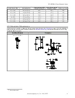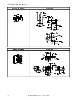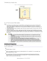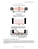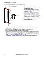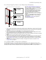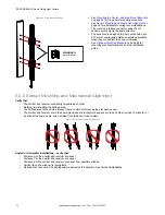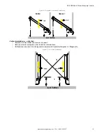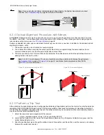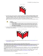
Figure 14. Adjacent Reflective Surfaces
Do not position reflective surfaces within the shaded area
Operating Range
(R)
At installed operating range (R):
d = 0.0437 x R (m or ft)
Receiver
Emitter
d
d
Operating range 0.1 to 3 m (4 in to 10 ft): d = 0.13 m (5 in)
Operating range > 3 m (>10 ft): d = 0.0437 x R (m or ft)
side view
d
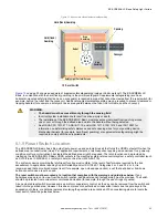
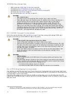
Optical Short Circuit
REFLECTIVE SURFACE
Increasing the size of the test piece to block
extra beams causes a blocked condition.
The size of the test piece required to do this
determines the actual resolution.
At the midpoint of the defined area, a test piece (represented by the darker
circle) with the specified system resolution does not cause a blocked
condition, due to an optical short circuit. Alignment indicator LEDs are ON
green and the OSSDs are ON.
For 0.1 m to 3 m (4 in to 10 ft) Operating range: d = 0.13 m (5 in)
For Operating range > 3 m (> 10 ft): d = 0.0437 × R (m or ft)
At the midpoint of the defined area, a test piece (represented by the darker circle) with the specified system resolution does
not cause a blocked condition due to an optical short circuit. Green Alignment indicator lights are On and the OSSDs are On.
Increasing the size of the test piece to block additional beams causes a blocked condition. The size of the test piece required
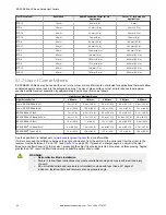
to do this determines the actual resolution. Use the table below to calculate Dpf or Factor "C" when a shiny surface causes
an optical short circuit.
EZ-SCREEN
®
LS Basic Safety Light Curtain
www.bannerengineering.com - Tel: + 1 888 373 6767
27

