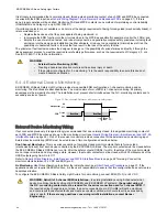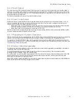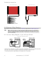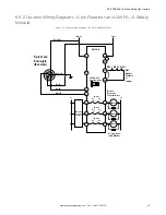
5.2.2 Mounting the End-Mount Brackets
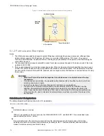
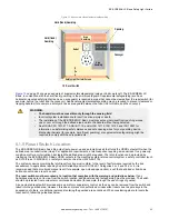
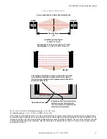
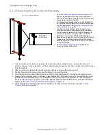
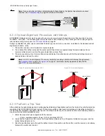
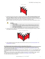
Figure 22. End-Mount Brackets
EZLSA-MBK-11
End Mount Bracket
•
Sensor Mounting and Mechanical Alignment
on
page 34 for additional mounting recommendations.
•
The machine interface connector ends of both sensors
must point in the same direction.
•
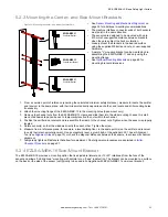
Two brackets are supplied with each EZLSA-MBK-11
kit. Additional EZLSA-MBK-12 center-mount bracket(s)
may be required (see
Mounting the Center- and Side-
on page 33).
•
Loosely mount the brackets to the desired surface
using the bolts and nuts supplied with the bracket kit,
or user-supplied hardware. (Use the M5 hardware to
mount the brackets to the light curtain; use the M6
hardware to mount the brackets to the machine.)
•
Brackets are designed to mount directly to MSA Series
stands using the hardware supplied with the stands.
•
Brackets may face in (shown on bottom) or out (shown
on top), as desired.
•
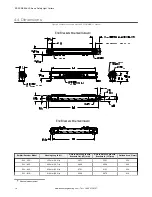
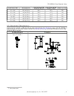
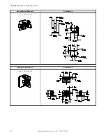
on page 68 for
mounting bracket dimensions.
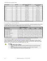
1. From a common point of reference (ensuring the calculated minimum safety distance), measure to position the
emitter and receiver in the same plane, with their midpoints directly opposite each other, and locate and drill mounting
holes if necessary.
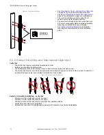
2. Slide the end-mount bracket onto the side mounting channels and tighten the channel screws.
3. Position the emitter and receiver, and attach the flange to the mounting holes.
4. Verify that the sensor windows directly face each other by rotating the sensor(s), then tighten the bracket screws.
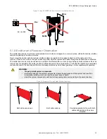
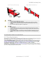
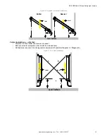
5. Measure from a reference plane, for example, a level building floor, to the same point(s) on the emitter and receiver
to verify their mechanical alignment. Use a carpenter’s level, a plumb bob, or the optional LAT-1 Laser Alignment
Tool (see
on page 70) or check the diagonal distances between the sensors, to achieve mechanical
alignment. See
Sensor Mounting and Mechanical Alignment
on page 34.
on page 37.
EZ-SCREEN
®
LS Basic Safety Light Curtain
32
www.bannerengineering.com - Tel: + 1 888 373 6767

