February 12, 2024
Q90R R-GAGE® Radar Sensor Instruction Manual
© Banner Engineering Corp. All rights reserved.
11
Advanced Target
Minimum Active Sensing Range
: Sensor ignores anything from the face of the sensor to this defined range.
Maximum Active Sensing Range
: Sensor ignores anything past this defined range.
Measurement Hold: A rate of change filter to smooth the output and reduce chatter. For more information,
see
Using Measurement Hold Example
Maximum Distance Increase Hold Time: The period of time the sensor holds its last measurement and output status if the
measurement changes more than the configured max distance increase. Available when
Measurement Hold is set to
enabled.
Maximum Distance Decrease Hold Time: The period of time the sensor holds its last measurement and output status if
the measurement changes more than the configured max distance decrease. Available when
Measurement Hold is set to
enabled.
Maximum Distance Increase: The allowed limit the measurement can increase, or move farther away from the sensor,
before initiating the
Measurement Hold
. Setting this to zero disables it. Available when
Measurement Hold
is set to
enabled.
Maximum Distance Decrease: The allowed limit the measurement can decrease, or move closer to the sensor, before
initiating the
Measurement Hold
. Setting this to zero disables it. Available when
Measurement Hold
is set to enabled.
Sensor Polarity
Define the output and remote input signal type.
Sensor Lockout
Remote Input (Gray Wire)
: Enable or disable the remote input wire.
LED Enable/Disable
Enable or disable the LEDs on the sensor
The following are the parameters on the Analog tab on the Sensor Settings
pane. This tab is available for analog models.
Target Position
Positive
Slope
Near
Window
Far
Window
Analog Output (mA)
20
4
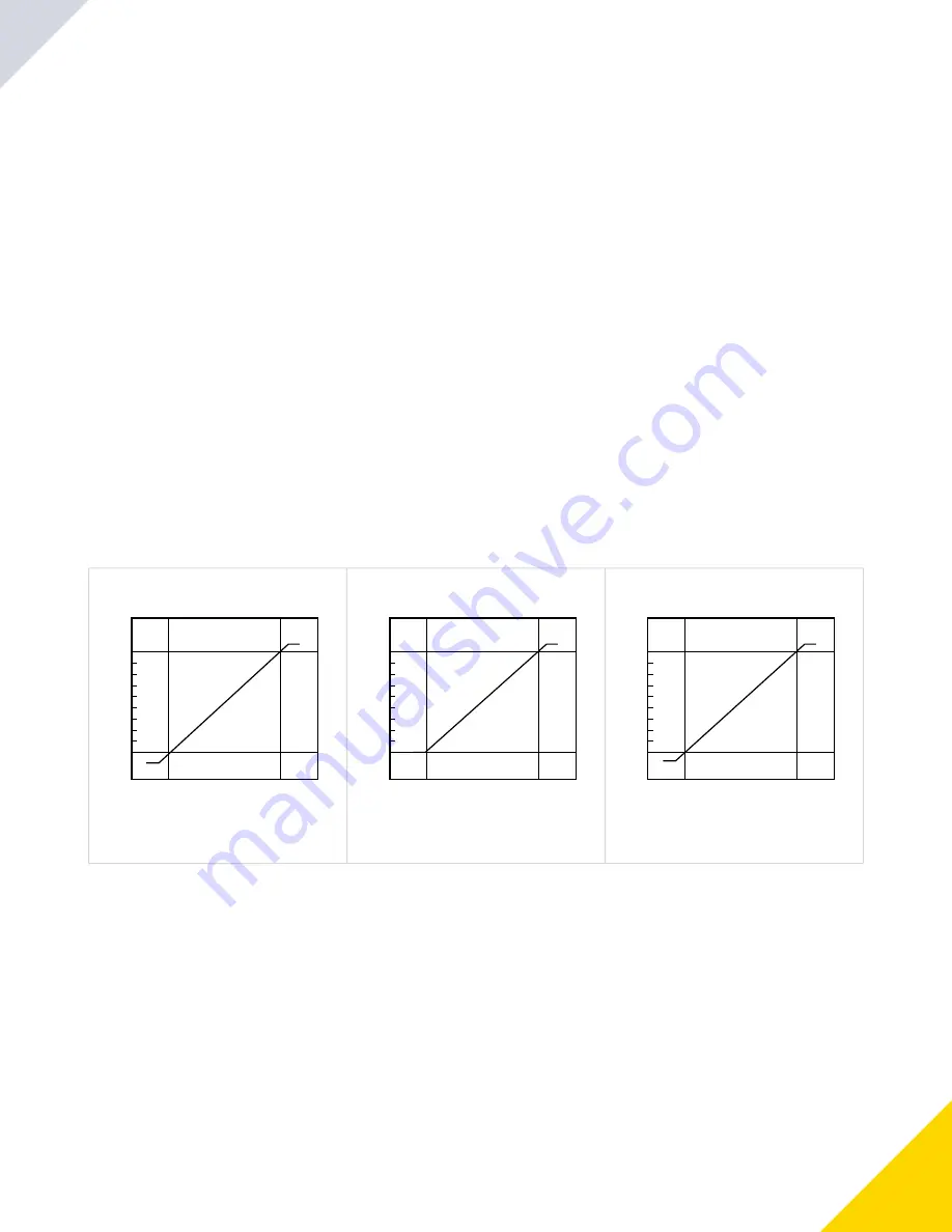
The analog current output tracks slightly beyond
each window limit (from 3.8 mA to 20.2 mA)
Target Position
Positive
Slope
Near
Window
Far
Window
Analog Output (V DC)
10
0
The analog current output tracks slightly beyond the
upper window limit (up to 10.2 V)
Target Position
Positive
Slope
Near
Window
Far
Window
Analog Output (V DC)
4.5
0.5
The analog current output tracks slightly beyond
each window limit (0V - 5V)
Analog Span
Define the outer limits of the analog range. This can be used to create a positive or negative slope.
Analog output options:
Current: 4 mA to 20 mA
Voltage: 0 V to 10 V or 0.5 V to 4.5 V
Analog Tab
4.4.2
Slope—Current-Sourcing
Models
Figure 7.
Slope—Voltage-Sourcing
Models, 0 V to 10 V
Figure 8.
Slope—Voltage-Sourcing
Models, 0.5 V to 4.5 V
Figure 9.
FINAL DRAFT
Summary of Contents for R-GAGE Q90R
Page 22: ...22 F I N A L D R A F T...
Page 28: ...28 F I N A L D R A F T...


