
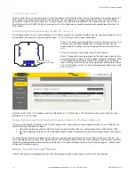
2. Remove the cover from the housing without damaging the ribbon cable or the pins the cable plugs into.
3. Gently unplug the ribbon cable from the board mounted into the bottom housing.
4. Remove the black cover plate from the bottom of the device's cover.
The DIP switches are located behind the rotary dials.
After making the necessary changes to the DIP switches, place the black cover plate back into
position and gently push into place. Plug the ribbon cable in after verifying that the blocked hole
lines up with the missing pin. Mount the cover back onto the housing.
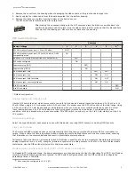
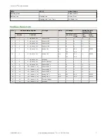
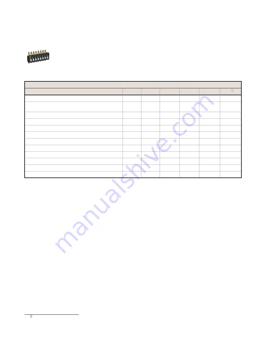
DIP Switch Settings
Switches
Device Settings
1
2
3
4
5
6 1
900 MHz transmit power level: 1 Watt (30 dBm)
OFF*
900 MHz transmit power level: 250 mW (24 dBm), DX80
compatibility mode
ON
Modbus or UCT configured (overrides DIP switches 3-8)
OFF*
DIP switch configured
ON
Inputs sourcing (PNP)
OFF*
Inputs sinking (NPN)
ON
Link loss output: zero
OFF*
OFF*
Link loss output: one
OFF
ON
Link loss output: hold last state
ON
OFF
Link loss output: user configuration
ON
ON
0 to 20 mA scale
OFF*
4 to 20 mA scale
ON
* Default configuration
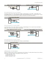
Analog Input and Output Scale
Use the DIP switch to select which current scale to use for all the device's analog inputs and outputs: 0 to 20 mA or 4 to
20 mA. When using a 4-20 mA sensor with a 0-20 mA input, the sensor uses the 4-20 mA section of the total range. Using
a 4-20 mA with a 0-20 mA input allows you to determine when you have an error condition with the sensor. A normal
input reading between 4 and 20 mA indicates a functioning sensor whereas a value below 4 mA indicates an error
condition, such as a broken wire or loose connection. This DIP switch is used only on the 0 to 20 mA models, not the 0 to
10V models.
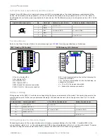
Discrete Input Type
Select the type of discrete input sensors to use with this device: sourcing (PNP) sensors or sinking (NPN) sensors.
Link Loss Outputs
The SureCross DX80 wireless devices use a deterministic radio link time-out method to address RF link interruption or
failure. When a radio link fails, all pertinent wired outputs are sent to defined states until the link is recovered, ensuring
that disruptions in the communications link result in predictable system behavior.
Following a radio link time-out, all outputs linked to the Node in question are set to de-energize (discrete outputs to zero,
analog outputs to 0 mA or 4 mA), energize (discrete outputs to one, analog outputs to 20 mA), or to hold the last stable
state/value. Use the DIP switches to select the link loss output state.
Modbus/User Configuration Tool (UCT) or DIP Switch Configured
In Modbus/UCT Configured mode, the device parameters are changed using the User Configuration Tool (UCT) or a Modbus
command. All DIP switch positions are ignored. In DIP Switch Configured mode, use the DIP switches to configure the
parameters listed in the table.
1 Not used when configured for 0-10 V I/O.
Sure Cross
®
Performance Node
P/N 155862 Rev. G
www.bannerengineering.com - Tel: +1-763-544-3164
3


