background image

Preliminary Information 

Banner Engineering Corp 

 Minneapolis, MN USA 


www.bannerengineering.com


 Tel: 763.544.3164 

Sensonix Incorporated 

 Plymouth, MN USA 

1 of 18


www.sensonix.com


 763.519.7042 

RF by


DX80 Gateway Installation & Operation Manual 


Operates in 902-928MHz ISM 
Spectrum


FHSS operation 


RF configurations – up to 150 mw 


External antenna connection 


RS232 / RS485 


2 Analog In (4-20ma) 


2 Analog Out (4-20ma) 


2 Digital In 


2 Digital Out 


10-30v DC 


LCD, Control buttons, LED 
indicators 


Stand alone operation 


DX80 - NEMA 6, IP67 enclosure 


The gateway and endpoint nodes communicate over multiple wireless channels within the 902-928MHz 

ISM Spectrum.  Different configurations of internal & external antennas and different RF power options 
allow you to customize the wireless range from a few feet to > 10000’. The implementation of FHSS 
methodology allows for reliable communications even in harsh industrial environments. The gateway 
station and endpoint nodes communicate with acknowledge handshaking to verify reception of data. Error 
checking is also performed to validate the data transmission.  

 
The Gateway and Endpoint node communications always collect signal strength information. The 

collected data can help gauge the strength and performance of the wireless signals. The received signal 
strength can be adjusted by various parameters such as the TX power settings and Receiver Sensitivity 
Modes. Hardware configurations can also impact the signal strength, such as internal / external antenna and 
antenna placement.  


Features 

Summary of Contents for SureCross DX80

Page 1: ...ions of internal external antennas and different RF power options allow you to customize the wireless range from a few feet to 10000 The implementation of FHSS methodology allows for reliable communic...

Page 2: ...able All DX80 mechanical enclosures Model Description Euro Connectors High Profile Low Profile LPGW1 Line Powered Gateway 1 female 1 male X LPGW2 Line Powered Gateway 1 male 8 pin X LPEN1 Line Powered...

Page 3: ...erengineering com Tel 763 544 3164 Sensonix Incorporated Plymouth MN USA 3 of 18 www sensonix com 763 519 7042 Junction Box Junction box models euro connectors glands Euro style connector or glands Mo...

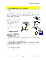
Page 4: ...t Panel Operation Avoid placement of the wireless units in extreme temperatures high vibration and high shock areas The DX80 is IP67 compliant and designed for all types of environments but continued...

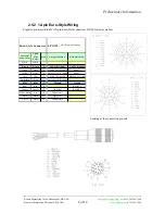
Page 5: ...r association table identifies all wires for the DX80 Gateway 2 5 1 8 pin Euro Style Wiring models LPGW2 BPDEN1 Signal to pin association for 8 pin Euro Style connectors DX80 Gateway models DX80 inter...

Page 6: ...n pin end Internal Wire Color Cable Wire Color Pin Euro QD1 female Euro QD2 male White White 1 Brown Brown 2 10 30Vdc Output 10 30Vdc Input Green Green 3 Analog In1 4 20mA RS485 Yellow Yellow 4 Analog...

Page 7: ...ead Discrete Inputs 1 2000 contiguous status of discrete inputs Modbus Cmd 3 0x3 Read Holding Registers 1 125 contiguous block of holding regs Modbus Cmd 4 0x4 Read Input Registers 1 125 contiguous bl...

Page 8: ...us slave number the gateway rotary switches indicate the Modbus slave number 01 99 During Site Survey operations the gateway switches define the node ID number the node rotary switches define the node...

Page 9: ...switches 00 Network ID set to a common value for the entire wireless network The factory default is 01 and will work for most single network installations See Setting the Network ID to change the netw...

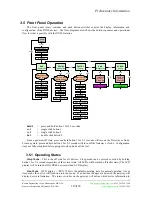
Page 10: ...Rotary switches define device Production high Production low sc 1 dc 2 dc 2 Config Start RF Baud Network ID ModBus Baud ModBus Slave ID hold 1 hold 1 hold 1 press and hold button 1 for 2 3 seconds sc...

Page 11: ...under the CONFIG menu The RF message can be one of several informational messages about the RF link between the gateway and node NO RF RF OFF RF SYNC and RF OK are the RF messages NO RF indicates the...

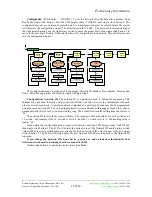
Page 12: ...nk RED to indicate you are now in Site Survey Start Now set the rotary switches to a node number to perform the Site Survey testing Then single click button 1 to activate the node defined by the rotar...

Page 13: ...Enter new value sc 2 LCD Display Current value Switch value Use Button 1 to Set NAME3 2 1 dc 2 sc 1 The configuration menu is made up of 4 sub menus Network ID Modbus Slave number Gateway and Node Se...

Page 14: ...LV and then single click button 2 The LCD will display the current value of the Modbus Slave number and the rotary switch values When the rotary switches are set correctly for the new Modbus Slave num...

Page 15: ...nce The DX80 family of products is designed to be IP67 compliant and maintenance free Annual cleaning and inspection is always recommended When inspecting the equipment watch for housing cracks residu...

Page 16: ...opping FHSS configurable of channels Rx Sensitivity To 110 dBm Antenna Connector External Reverse Polarity SMA 50 ohms Operating Temperature Range Electronics 40C to 85C LCD 30C to 70C LCD reduced vis...

Page 17: ...ration This equipment compiles with part 15 of the FCC rules Any changes or modifications not expressly approved by the manufacturer could void the user s authority to operate the equipment Antenna us...

Page 18: ...lymouth MN USA 18 of 18 www sensonix com 763 519 7042 9 Messages Endpoint Node RF link status messages RF OK RF Sync RF OFF NO RF Warning Error Messages LOWBAT Low battery condition replace battery S...

Reviews: