Preliminary Information
Banner Engineering Corp
•
Minneapolis, MN USA
www.bannerengineering.com
•
Tel: 763.544.3164
Sensonix Incorporated
•
Plymouth, MN USA
12 of 18
www.sensonix.com
•
763.519.7042
Diagnostics
(LCD display = ‘DIAG’) The diagnostic menu is a password protected area. A 4-digit
password must be entered before the system will enter into the diagnostics menus. The default password is
‘0000’. The password is entered starting at the right most character; use the right rotary switch to enter the
proper digit, then single click button 2 to move to the next digit. When all four digits have been properly
entered, double click button 2 to enter the site survey diagnostic.
The Site Survey mode can be used to judge the quality of the RF communications link between the
gateway and any node. Site Survey mode can only be activated from the gateway menu.
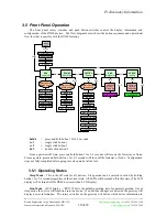
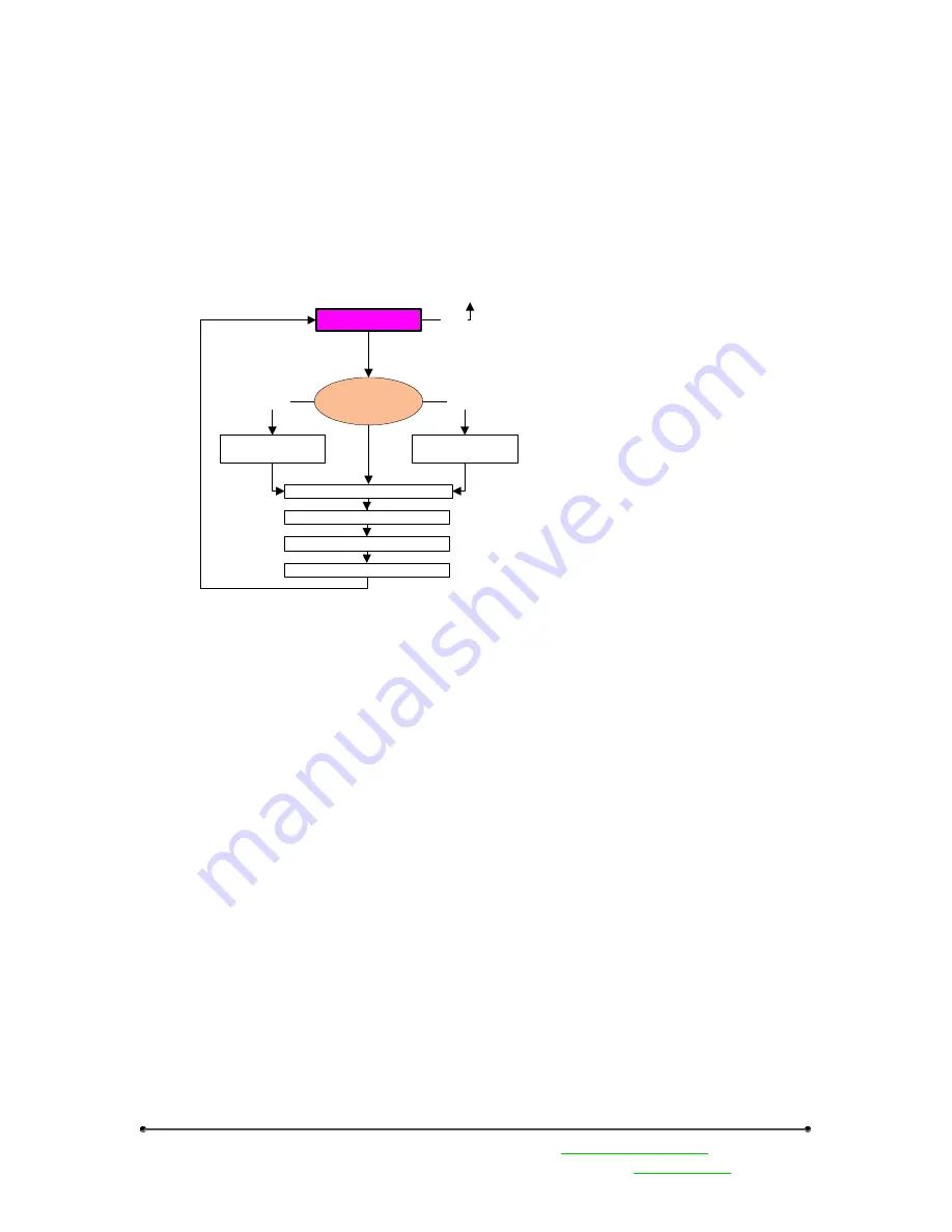
The gateway LED1 and LED2 will alternately blink RED to indicate you are now in Site Survey Start.
Now set the rotary switches to a node number to perform the Site Survey testing. Then single click button 1
to activate the node defined by the rotary switches.
Site Survey Start
Excellent Reception Total
Good Reception Total
Poor Reception Total
Rotary switches
define device
Activate Device &
Reset Totals
sc.1
Missed Packet Total
Deactivate
Device & Reset
Totals
dc.1
dc.2
This will cause the LCD on the front panel of both devices (gateway and node) to display the signal
strength for the wireless RF link. A group of 100 data packets are sent at different frequencies between the
gateway and the node. The LCD display will show the breakdown of total missed packets, total poor
reception packets, total good reception packets and the total number of excellent reception packets.
After 100 data packets the whole process is repeated. The LCD display is continually updated with the
running totals for each category.
When testing the communication signal link using site survey, make sure to keep all wireless units
separated by at least 3 feet.


