Preliminary Information
Banner Engineering Corp
•
Minneapolis, MN USA
www.bannerengineering.com
•
Tel: 763.544.3164
Sensonix Incorporated
•
Plymouth, MN USA
8 of 18
www.sensonix.com
•
763.519.7042
3 Setup & Operation
3.1 DX80 Front Panel
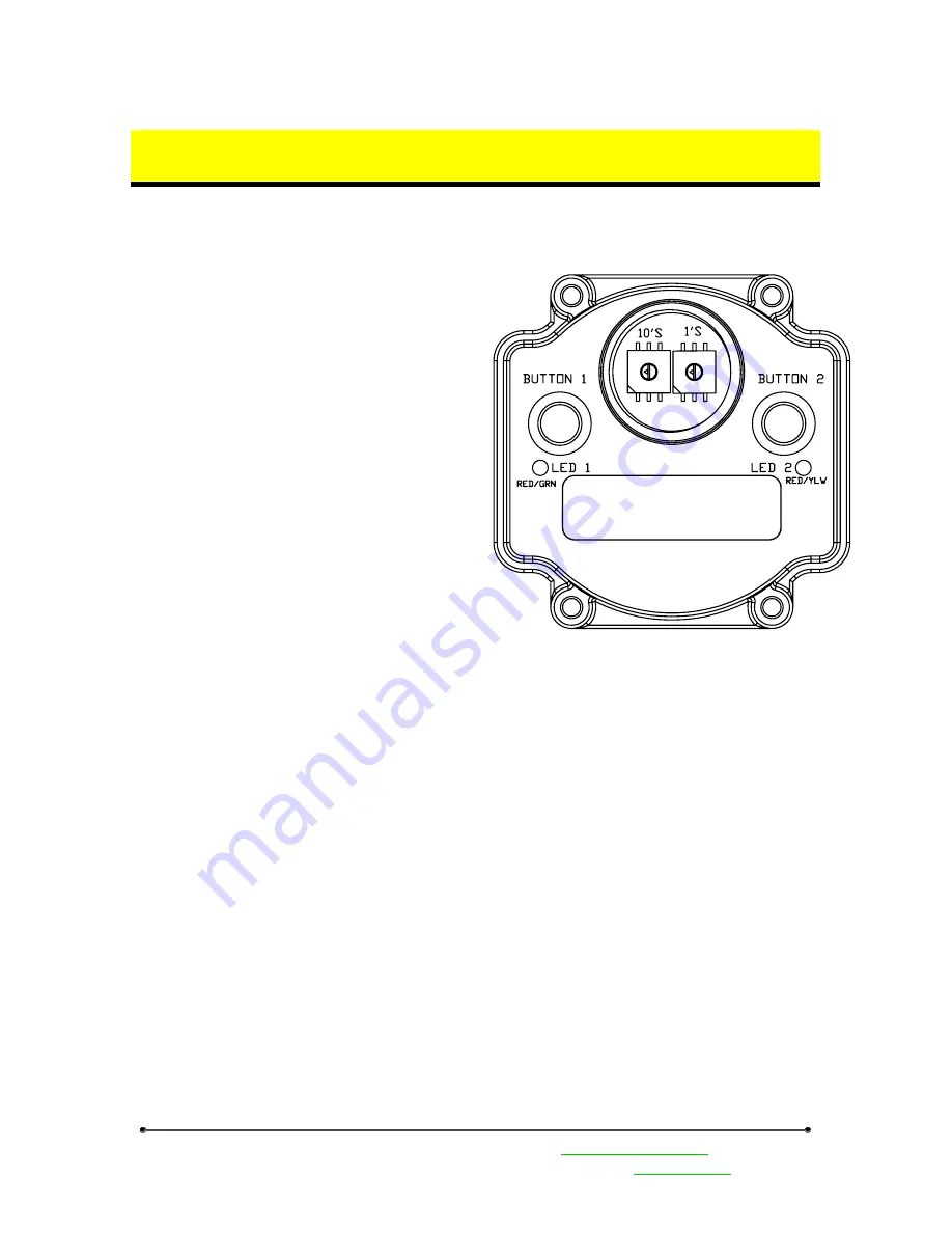
The DX80 front panel picture helps identify
each switch, button and LED. The rotary switches in
the middle of the round window are identified as a
10’s switch (left switch) and a 1’s switch (right
switch). The value for each rotary switch is 0 – 9.
The rotary switches define different parameters
depending upon the current operating state and
whether the device is a gateway or node.
During Run Mode the gateway rotary switches
define the device information to display; the node
switches indicate the node ID number.
During configuration of the Network ID, the
rotary switches indicate the network ID number on
both the gateway and the node.
During configuration of the Modbus slave
number the gateway rotary switches indicate the
Modbus slave number 01-99.
During Site Survey operations the gateway
switches define the node ID number; the node rotary
switches define the node ID number.
The gateway front panel LED’s are used to display information about the Modbus serial
communications
LED1
•
‘GREEN’ when power is applied and the gateway is operational.
•
‘RED’ indicates a system error has occurred. Review the LCD display for further
information.
LED2
•
‘YELLOW’ signifies a frame reception or sending.
•
‘RED’ signals an internal Modbus error has occurred.
•
Flashing ‘RED’ indicates a communications fault or configuration error.
The gateway LCD panel will display a variety of information about the gateway and wireless system.
3.2 Power on / Power Off
The gateway and nodes can be powered up or powered down with button 1. When the device is
powered down (sleep mode), depress button 1 for 2-3 seconds, the device will activate. Holding down
button1 for 2-3 seconds when the device is active will cause the device to power off. The wireless devices
are not operational when in Sleep Mode.


