16
P/N 134421
Banner Engineering Corp. • Minneapolis, MN U.S.A.
www.bannerengineering.com • Tel: 763.544.3164
SureCross™ DX80 Web Configurator
Instruction Manual
RF Devices Tab
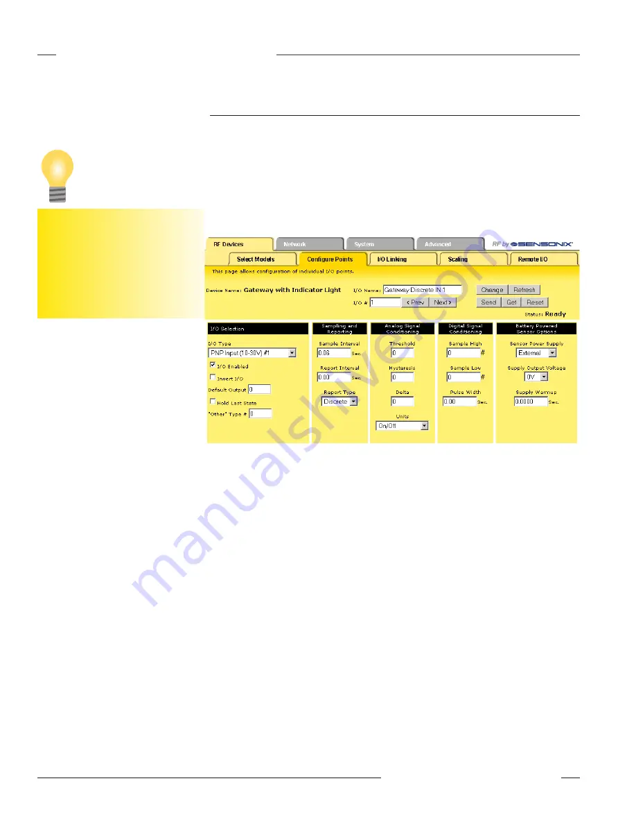
Expanded Configure Points
Most I/O point parameters are changed using the expanded view of the
Configure Points
tab. To
access this expanded view, which displays all parameters for the I/O point selected, click on the I/O
number hyperlink from the
Configure Points
tab. Several parameters on the expanded view also
appear in the standard
Configure Points
screen and can be modified from either screen.
Saving Changes to the XML File
To save the changes to the XML file, go to the
System > Setup > Config File
page and click the
Save button. Changes made by clicking the Change button are temporary until the changes are
saved permanently in the configuration file.
I/O Selection
Default Output: The default output parameters define what an I/O point is set to during selected
default conditions, such as an RF link failure.
Hold Last State: When communication fails, the I/O point retains the last value recorded instead of
the default output value.
Invert I/O: Selecting this checkbox inverts the digital representation of the I/O.
I/O Enabled: Select the checkbox to enable the individual I/O point. If the checkbox is not selected,
that I/O point is disabled. This checkbox is also on the primary screen.
I/O Type: Select the I/O type from the drop-down list. The drop-down list includes all options
available for the entire DX80 line. Not all I/O types included in the drop-down list are applicable
for any given device. Refer to the device data sheet to determine which options are available for a
given device.
“Other” Type #: Occasionally some newly designed and released devices will use I/O types not
yet listed in the drop-down list for I/O Type. When this happens, Banner Engineering applications
engineers will supply the “other” type number. Select
Other
from the I/O Type drop-down list and
enter the I/O type number supplied by Banner Engineering into this field.
Sampling and Reporting
Report Interval: The report interval defines how often the Node communicates the I/O status to the
Gateway. Enter the report interval in seconds, and the interface rounds the value to the nearest 62.5
millisecond increment.
For discrete inputs, setting the report interval to zero sets the system to report only when the values
have changed, also called
reporting on change of state
. When discrete inputs are set up with a
To save the changes to the XML file,
go to the
System > Setup > Config File
page and click the Save button.
Changes made by clicking an Update
or Change button are temporary until
the changes are saved permanently in
the configuration file.
Tip


