background image

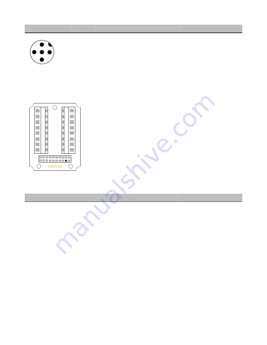
Wire No.

Wire Color

10 to 30V dc Powered Nodes

Battery Powered Nodes

1

2

3

4

5

1

Brown

10 to 30V dc

2

White

3

Blue

dc common (GND)

dc common (GND)

4

Black

5

Gray

3.6 to 5.5V dc

Connecting dc power to the communication pins will cause permanent damage. For FlexPower devices, do not apply more than 5.5V to
the gray wire.

Terminal Block (IP67)

A4+
A2-

A2+
GND

PWR
DO2

DI2

A3+
A1-

A1+
GND

PWR
DO1

DI1

A4- A3-

Ax+ and Ax-. Analog IN x. Analog inputs for devices requiring more than
one connection, such as thermocouples or RTDs. When there is no Ax-,
use Ax+ as an analog input.
DIx. Discrete IN x.
DOx. Discrete OUT x.
GND. Ground/dc common connection.
PWR. Power, 10 to 30V dc power connection.

DX80...C Wiring

Wiring power to the DX80...C models varies depending the power requirements of the model.

Terminal Label Gateway, DX85 *

10 to 30V dc Powered Nodes

Battery Powered Nodes **

V+

10 to 30V dc

10 to 30V dc

Tx/+

RS485 / D1 / B / +

V-

dc common (GND)

dc common (GND)

dc common (GND)

Rx/-

RS485 / D0 / A / -

B+

3.6 to 5.5V dc

* Connecting dc power to the communication pins will cause permanent damage.
** For FlexPower devices, do not apply more than 5.5V to the gray wire.

Terminal Block (IP20)

For the DX8x...C models, PWR in the wiring diagram refers to V+ on the wiring board and GND in the wiring diagram refers to V- on the
wiring board.

SureCross Performance FlexPower Node


P/N 155863_web
Rev. C

www.bannerengineering.com - tel: 763-544-3164

5

Summary of Contents for SureCross Performance DX80N9X2S-P3 FlexPower

Page 1: ...te list of accessories refer to Banner Engineering s website www bannerengineering com surecross Models Frequency Power Housing I O DX80N9X2S P3 900 MHz ISM Band 10 to 30V dc or battery supply mod ule...

Page 2: ...its Modbus RTU RS 485 connection is a Modbus slave to a Modbus RTU host controller the wireless network may contain up to 47 Nodes in a single wireless network and the Gateway holds the Modbus regist...

Page 3: ...To access the internal DIP switches follow these steps 1 Unscrew the four screws that mount the cover to the bottom housing 2 Remove the cover from the housing without damaging the ribbon cable or the...

Page 4: ...600 degrees Fahrenheit or 1600 degrees Celsius switch the DIP switch to the ON position and use low resolution mode In high resolution the device cannot store values larger than 1600 Temperature Units...

Page 5: ...OUT x GND Ground dc common connection PWR Power 10 to 30V dc power connection DX80 C Wiring Wiring power to the DX80 C models varies depending the power requirements of the model Terminal Label Gatewa...

Page 6: ...optional 2 RS 485 D1 B RS 232 Tx 3 dc common GND dc common GND 4 RS 485 D0 A RS 232 Rx The BAT connection is a low voltage connection to the internal battery Remove the internal battery if a low volta...

Page 7: ...ocouples are available by configuring the Node Thermocouple Range F Range C Type B 212 to 3 272 F 100 to 1 800 C Type C 32 to 4 208 F 0 to 2 320 C Type E 58 to 1 832 F 50 to 1 000 C Type J 292 to 1 38...

Page 8: ...an integrated battery ship from the factory in storage mode to conserve the battery To wake the device press and hold button 1 for five seconds To put any FlexPower or integra ted battery SureCross r...

Page 9: ...isk of explosion if the battery is re placed incorrectly 4 After replacing the battery allow up to 60 seconds for the device to power up Properly dispose of your used battery according to local regula...

Page 10: ...FF Condition PNP Less than 5V NPN Greater than 2V or open Thermocouple Inputs Sample Rate 8 seconds Report Rate 32 seconds Accuracy 0 1 of full scale reading 0 8 C Resolution 0 1 C 24 bit A D converte...

Page 11: ...the most recent version of any documentation refer to our website www bannerengineering com 2006 2010 Banner Engineering Corp All rights reserved Banner Engineering Corp Limited Warranty Banner Engine...

Reviews: