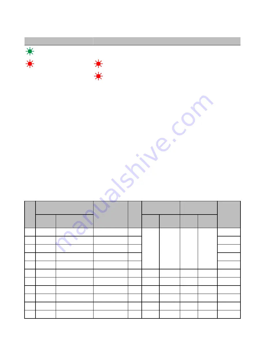
verify all radios and antennas are at least two meters apart or the communications may fail. This table lists the LED behavior for the Node
models with two LEDs.
LED 1
LED 2
Node Status
(green flashing, 1/sec)
Radio Link Ok
(red flashing)
(red flashing, 1/sec)
Device Error
(red flashing, 1 per 3 sec)
No Radio Link
Mixing Performance and Non-Performance Radios in the Same Network
To comply with federal regulations, the 150 mW radios and 1 Watt radios communicate differently. To mix Performance radios with non-
Performance radios:
• Performance radios must operate in 250 mW mode, not 1 Watt mode (DIP switch 1 ON)
• Non-Performance radios must be set to use Extended Address Mode (DIP switch 1 ON)
For more detailed instructions about setting up your wireless network, refer to the Quick Start Guide, Banner document number 128185.
For more information about using Performance and non-Performance radios within the same network, refer the technical note titled
Mixing Performance Radios and 150 mW Radios in the Same Networklisted on the FAQ/Knowledgebase section of Banner's Wireless
Sensor Networks website.
Storage Mode and Sleep Mode
While in storage mode, the radio does not operate. All SureCross
®
radios powered from an integrated battery ship from the factory in
storage mode to conserve the battery. To wake the device, press and hold button 1 for five seconds. To put any FlexPower
®
or integra-
ted battery SureCross radio into storage mode, press and hold button 1 for five seconds. The radio is in storage mode when the LEDs
stop blinking, but in some models, the LCD remains on for an additional minute after the radio enters storage mode. After a device has
entered storage mode, you must wait one minute before waking it.
During normal operation, the SureCross radio devices enter sleep mode after 15 minutes of operation. The radio continues to function,
but the LCD goes blank. To wake the device, press any button.
Modbus Register Table (High Resolution Mode)
I/O
Modbus Holding Register
I/O Type
Units I/O Range
Holding Register
Value
Terminal
Block La-
bels
Gateway
Any Node
Min.
Temp
Max.
Temp
Min.
(Dec.)
Max.
(Dec.)
1
1
1 + (Node# × 16)
Thermocouple IN 1
°F/°C
-1638.3
+1638.4
-32768
32767
A1+/A1-
2
2
2 + (Node# × 16)
Thermocouple IN 2
°F/°C
A2+/A2-
3
3
3 + (Node# × 16)
Thermocouple IN 3
°F/°C
A3+/A3-
4
4
4 + (Node# × 16)
Thermocouple IN 4
°F/°C
A4+/A4-
5
5
5 + (Node# × 16)
Thermistor IN
°F/°C
(on board)
6
6
6 + (Node# × 16)
Discrete IN 1, 2 *
-
0
3
0
3
DI1, DI2
7
7
7 + (Node# × 16)
Reserved
8
8
8 + (Node# × 16)
Device Message
9
9
9 + (Node# × 16)
Discrete OUT 1
-
0
1
0
1
DO1
...
15
15
15 + (Node# × 16)
Control Message
SureCross Performance FlexPower Node
8
www.bannerengineering.com - tel: 763-544-3164
P/N 155863_web
Rev. C


