I/O
Modbus Holding Register
I/O Type
Units I/O Range
Holding Register
Value
Terminal
Block La-
bels
Gateway
Any Node
Min.
Temp
Max.
Temp
Min.
(Dec.)
Max.
(Dec.)
16
16
16 + (Node# × 16)
Reserved
In high resolution mode, the temperature = (Modbus register value) ÷ 20. In low resolution mode, the temperature is (Modbus register
value) ÷ 2.
Temperature values are stored as signed values in the Modbus register. A 0 in the register is interpreted as 0°; and -32767 (65535
unsigned) in the register (0xFFFF) is interpreted as −1 ÷ 20 = −0.05° in high resolution mode and −1 ÷ 2 = −0.5° in low resolution mode.
* The discrete inputs 1 and 2 are bit-packed into register 6, with discrete IN 1 using bit 0 and discrete IN 2 using bit 1. Because the two
discrete INs are bit packed, only discrete IN 1 may be mapped using the User Configuration Tool. To use both discrete inputs you must
use a host system.
Integrated Battery Replacement (DX80...E Models)
For outside or high humidity environments, conductive grease may be applied to the battery terminals to prevent moisture and corrosion
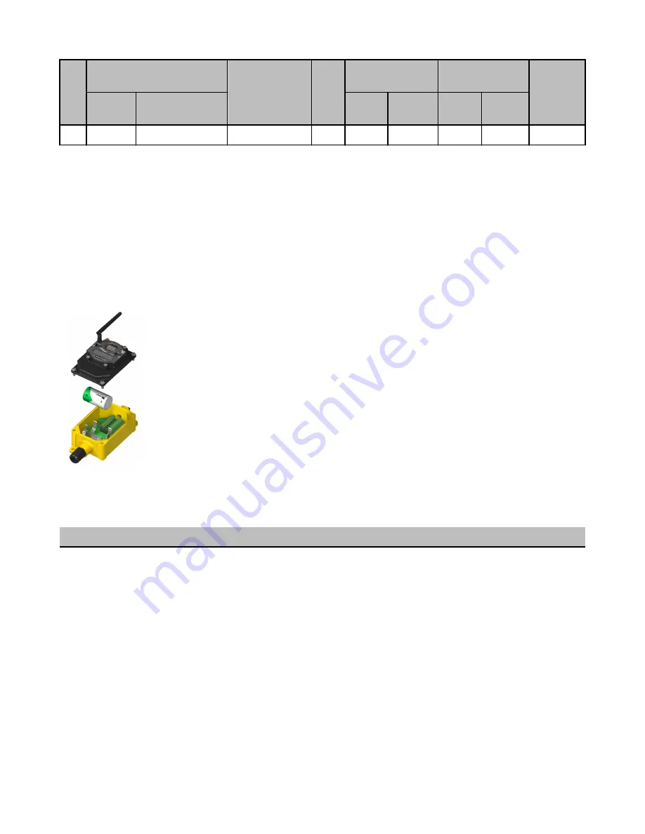
buildup. To replace the lithium "D" cell battery in any integrated housing model, follow these steps.
1. Remove the four screws mounting the face plate to the housing and remove the face plate. Do not
remove the radio cover from the face plate.
2. Remove the discharged battery and replace with a new battery. Only use a 3.6V lithium battery from
Xeno, model number XL-205F.
3. Verify the battery’s positive and negative terminals align to the positive and negative terminals of the
battery holder mounted within the case. Caution: There is a risk of explosion if the battery is re-
placed incorrectly.
4. After replacing the battery, allow up to 60 seconds for the device to power up.
Properly dispose of your used battery according to local regulations by taking it to a hazardous waste col-
lection site, an e-waste disposal center, or other facility qualified to accept lithium batteries. As with all
batteries, these are a fire, explosion, and severe burn hazard. Do not burn or expose them to high temper-
atures. Do not recharge, crush, disassemble, or expose the contents to water.
Replacement battery model number: BWA-BATT-001. For pricing and availability, contact Banner Engineering.
Specifications
Radio
General
Radio Range
900 MHz (1 Watt): Up to 9.6 kilometers (6 miles) *
2.4 GHz: Up to 3.2 kilometers (2 miles) *
Radio Transmit Power
900 MHz (1 Watt): 30 dBm conducted (up to 36 dBm
EIRP)
2.4 GHz: 18 dBm conducted, less than or equal to 20
dBm EIRP
900 MHz Compliance (1 Watt Radios)
FCC ID UE3RM1809: This device complies with FCC
Part 15, Subpart C, 15.247
IC: 7044A-RM1809
2.4 GHz Compliance
FCC ID UE300DX80-2400 - This device complies with
FCC Part 15, Subpart C, 15.247
Power*
DX80 and DX80...C Model Requirements: +10 to 30V
dc or 3.6 to 5.5V dc low power option (For European
applications: +10 to 24V dc, ± 10% or 3.6 to 5.5V dc
low power option)
DX80...E Model Requirements: 3.6V dc low power op-
tion from an internal battery or 10 to 30V dc
900 MHz Consumption: Maximum current draw is <40
mA and typical current draw is <30 mA at 24V dc. (2.4
GHz consumption is less.)
Housing
Polycarbonate housing and rotary dial cover; polyester
labels; EDPM rubber cover gasket; nitrile rubber, non-
sulphur cured button covers
Weight: 0.26 kg (0.57 lbs)
SureCross Performance FlexPower Node
P/N 155863_web
Rev. C
www.bannerengineering.com - tel: 763-544-3164
9


