8.3 Perform a Commissioning Checkout
Perform the Commissioning Checkout procedure as part of the SX installation (after it has been interfaced to the guarded
machine as described) or after changes are made to the system (either a new configuration of the SX system or changes to
the machine).
Perform the Commissioning Checkout procedure after:
•
Configuring the SX system with the configuration software
•
Connecting the SX system to the control system or safety switching device
•
Verifying the cover to the 4-pin M12/Euro-Style Ethernet connector is in place over the connector or a cable is
securely connected
Record the checkout results and store on or near the guarded machine as required by applicable standards.
WARNING:
•
There is a risk of unpredictable machine behavior at the initial start up of the machine.
•
Failure to follow these instructions could result in serious injury or death.
•
The Qualified Person must take precautions to ensure that no one is in or near the hazardous area
during these safety system tests.
1. Examine the guarded machine to verify that it is of a type and design compatible with the SX system. For a list of
appropriate and inappropriate applications, see
on p. 10.
2. Verify the SX system is configured for the intended application and all mounting hardware is secured.
3. Verify that the minimum safety (separation) distance from the closest hazard of the guarded machine to the Safety
Zone(s) is not less than the calculated distance. See
Minimum Safety (Separation) Distance for Stationary
on p. 34 and
on p. 38.
4. Verify that:
a) Access to any dangerous parts of the guarded machine is not possible from any direction not protected by the SX
system, hard guarding, or supplemental safeguarding; and
b) It is not possible for a person to stand between or climb over/under the protected Field(s) and the dangerous parts
of the machine, or stand on top of the SX system; or
c) Supplemental safeguarding and hard guarding, as described by the appropriate safety standards, are in place
and functioning properly in any space between the Safety Zone(s) and any hazard that is large enough to allow a
person to be undetected by the SX system.
5. Verify that all reset switches are mounted outside and in full view of the guarded area, out of reach of anyone inside
the guarded area, and that means of preventing inadvertent use is in place.
6. Examine the electrical wiring connections between the Scanner OSSD outputs and the guarded machine’s control
elements to verify that the wiring meets the requirements stated in
on p. 47 and
Connections to the Guarded Machine
7. Remove all obstructions from the Safety Zone(s). Apply power to the SX system. Verify that power to the guarded
machine is off.
•
If the SX system is configured for Start Interlock (Manual Power-Up)
, LED 1 will show green, LED 5 will be
on and the display shows RESTART (Interlock 1). Perform a manual reset (close the reset switch for 0.5 to 4.5
seconds, then open the switch) to turn on the OSSD outputs.
•
If the SX system is configured for Automatic Start (Automatic Reset)
, LED 1 will show GREEN and the
display will show GO, and the OSSD outputs turn on (after the restart delay time).
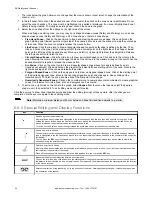
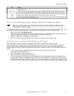
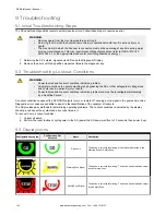
8. Observe the Diagnostic Display on remote scanner displays also (if configured).
•
Lockout
—Lockout information listed on the display.
•
Safety Zone interrupted
—Red STOP shown on display with direction of interruption also red.
•
Safety Zone Clear and OSSDs on
—Green GO shown on the display.
•
Start/Restart Interlock (OSSDs off, waiting for reset)
—Restart in a circle with Interlock below it shown on the
display.
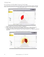
9. An interrupted Safety Zone (SZ) condition indicates that one or more objects are being detected within the active
protected Zone. To correct this situation, identify the interruption using the software's
Monitoring
mode or by
observing the area covered by the Safety Zone, and then remove all objects or realign the SX system. If the system is
in a Start/Restart Interlock (waiting for Reset) condition, perform a manual reset.
10. After the display shows the green GO, perform the trip test (
on p. 65) on each of the configured
Safety Zones on all scanners to verify proper system operation and to detect possible unmonitored areas. Verify that
if the Safety Zone boundary is identified (for example, marked on the floor), that it matches the corresponding Safety
Zone. Do not continue until the SX system passes the trip test. Do not expose any individual to any hazard during the
following checks.
SX Safety Laser Scanner
102
www.bannerengineering.com - Tel: + 1 888 373 6767


