•
Determine whether Zone Set switchover is required and identify the conditions for its use.
•
Determine whether the Reference Point function is required (at least three (3) reference points must be defined on
fixed surface(s)).
•
Determine the method and means of electrical interfacing dependent on the level of risk determined by the risk
assessment (e.g., OSHA/ANSI control reliability or ISO 13849-1 category 3 PLd).
2.3.4 Sample Applications
The SX Series Safety Laser Scanner is used to detect people who are approaching a hazardous area, before reaching it, to
prevent hazardous circumstance (i.e. mechanical movement) that may cause an accident.
The protective detection is done by defining a safety area (the red zone in the figures), whose shape and dimensions must
be designed according to the risk assessment of the machine. The user must consider the position of the hazardous points,
the shape of the machine and of the environment that surrounds it, and the time needed to stop the dangerous movement.
To better ensure people's safety, it is possible to define a warning area (the green zone in the figures): if a person or an
object is approaching too close to the safety area, the safety laser scanner can trigger warning devices. This warning area
cannot be used for safety purposes.
The following application examples should be considered just as references for instructional purposes.
Stationary Area Guarding (Horizontal Danger Zone Guarding)
Area Guarding uses a horizontal sensing field (i.e., Safety or Warning Zones) to continually sense an individual within a
safeguarded area. Area Guarding can reduce or eliminate the possibility of a pass-through hazard that could result in an
individual being exposed to unexpected machine startup or motion.
As an individual approaches, the Warning Zone (the green area) can illuminate a warning beacon or sound an alarm that the
Safety Zone (the red area) is about to be entered. In conjunction with markings on the floor, the use of a Warning Zone can
eliminate intermittent stopping due to individuals being unaware of the safeguarded area. When the Safety Zone is
encroached upon, a stop is issued and the hazard is brought to a safe state.
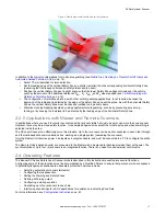
Figure 4. Horizontal stationary area guarding
Typical considerations for horizontal stationary area guarding:
•
In this example, the SX is mounted in the center of the operator work station to maximize the available size of the
Safety and Warning Zones. The SX is mounted directly to the cell's perimeter guarding fencing 300 mm above the
floor to prevent crawling under the Safety Zone.
•
In this example, physical damage is not expected because the fencing provides adequate protection. If interference
with the operator is expected, the Scanner can be recessed into the fencing to minimize exposure.
•
The typical manufacturing setting is well within the SX's environmental ratings.
•
The size and coverage of the Safety Zone must ensure that the hazard cannot be accessed by moving (reaching)
around, under, or over the Safety Zone. Access to the hazard is prevented by the fencing along the side of the Safety
Zone, which minimizes the required floor space.
•
For this example, assume a robot stopping time of 100 ms, SX response time of 62 ms, the response time of a safety
interfacing device is 25 ms (UM-FA-9A safety module). Because an individual can reach over the detection plane by
bending at the waist, the
Dpf
adder is equal to 1200 mm (U.S. formula) and the Measurement Tolerance Factor
(
Z
SM
) must be accounted for. This gives a safety distance of:
Ds = 1600 mm/s × (0.1s + 0.062s + 0.025s) + 1200
SX Safety Laser Scanner
12
www.bannerengineering.com - Tel: + 1 888 373 6767


