Z
amb
Retro Reflector Factor
—The additional distance needed to account for measurement errors due to light interference
(see section 3.x.4) and/or reflections from highly reflective or shiny surfaces that are present in the scanning plan.
•
No ambient interference Z
amb
= 0
•
Ambient Interferences present Z
amb
= 200 mm; for more information and how to determine the value for the SX5-B
model, refer to
on p. 30
Z
F
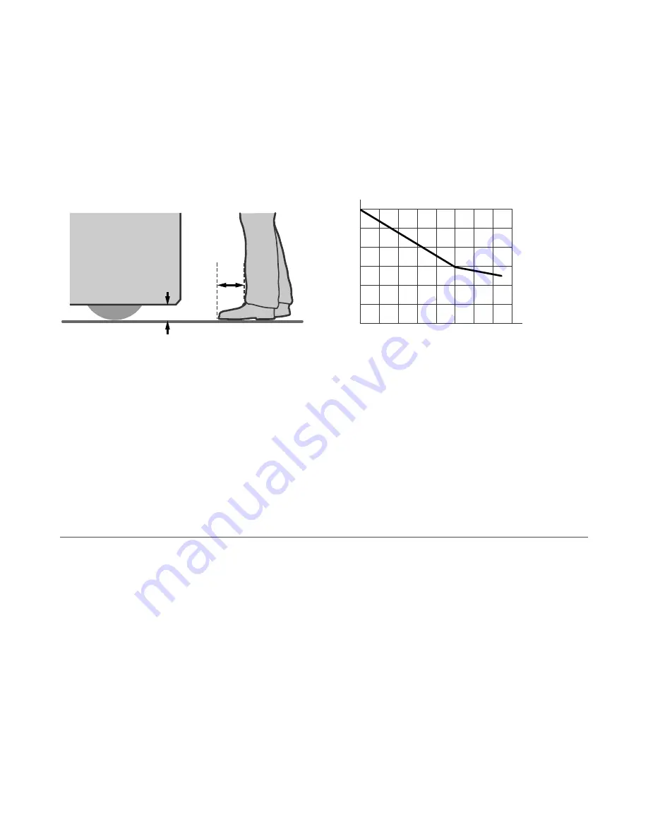
Mobile Vehicle (AGV) Ground Clearance
— The additional distance Z
F
is required if the mobile vehicle does not have
sufficient ground clearance (HF) such that there is no space under the vehicle or Scanner for the tips of feet. If the wheels
are mounted near the side wall, always add an additional distance Z
F
≥ 150 mm; otherwise Z
F
is determined according to the
following figure.
Figure 31. Diagram to determine the additional distance Z
F
with lack of floor clearance H
F
Mobile
Vehicle
Z
F
H
F
H
F
Z
F
20
40
60
80
100
120
20
0
0
40 60 80 100 120 140 160
Z
A
Application-Specific Additions
— Z
A
is the additional distance needed to account for factors that can otherwise affect
the safe application of the SX. Examples include:
•
Approach speed of an individual who is unaware of the vehicle's movement. ISO 13855 (Positioning of Safeguard
with Respect to Approach Speed) defines walking speed as 1600 mm/s (63 in/s), thus Z
A
= 1600 mm/s × (T
S
+ T
R
)
•
Additional clearance to avoid crushing, Z
A
= 500 mm (20 in) per ISO 13854 (EN349)
•
The effect of turning with long vehicles or trailers, resulting in large lateral travel
Multiple factors may or may not result in a cumulative effect: Z
A
= Z
A1
+ Z
A2
+ … Z
An
. Evaluate each factor to determine its
effect on all Additional Distance Factors (Z).
Additional Side Distance Z (Safety Zone Width)
— The width of the Safety Zone is determined by the width of the mobile
vehicle and the Additional Distance Factors (Z) as described. The distance Z may be different for the two sides and the
leading edge. The width of the Safety Zone must be greater than the width of the mobile vehicle.
Z = Z
SM
+ Z
amb
+ Z
F
+ Z
A
It is important that the factor Z
A
include the effect of turning with long vehicles or trailers, resulting in large lateral travel.
3.10 Mounting System Components
3.10.1 Mounting Your Scanner for Mobile Applications
The mounting of the SX should take into account:
•
the surface contour of the path of the vehicle including holes, bumps, inclines, ramps, and other variations in the
surface
•
deflection of springs or other vibration dampeners that could cause the plane of the Safety Zone to vary
•
unmonitored areas created by the installation of the SX
The point of mounting is typically in the center of the leading edge of the vehicle and is aligned horizontally to achieve a
consistent scanning height over the entire Safety Zone.
Mounting Height
— Mount the SX as low as possible to prevent people from passing beneath the sensing field by lying on
the floor. ISO 3691-4 and IEC 61496-3 recommend that the Safety Zone with a resolution of 70 mm be as near as possible to
the floor, but no greater than 200 mm (7.9 in) above the floor. In general, a height of 150 mm (5.9 in) has been recognized by
industry to be the most advantageous height above the floor.
SX Safety Laser Scanner
www.bannerengineering.com - Tel: + 1 888 373 6767
41


