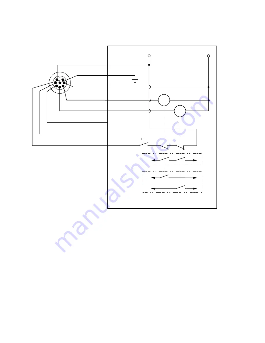
Wiring with Redundant FSD Inputs
Figure 39. Wiring with redundant FSD inputs
+24 V DC
0 V DC
OSSD1
OSSD2
n.c.
n.c.
Reset / Restart
FSD2
FSD1
Single-Channel
Safety Stop
Circuit
Dual-Channel
Safety Stop
Circuit
NOTE: Do not exceed OSSD maximum load
capacitance specification.
2 - Brown
8 - Red
7 - Blue
5 - Gray
6 - Pink
3 - Green *
1 - White *
4 - Yellow *
+24 V DC
Functional Earth
0 V DC
Scanner
8-pin Male
Euro-style
face view
* Functionality of pins 1, 3, and 4
is configured with the GUI
Note: This wiring diagram shows
pin 1 configured as a reset/restart.
Monitoring FSDs—FSDs must be monitored for proper operation. One-channel EDM can only be used when the scanner is
configured for manual reset.
SX Safety Laser Scanner
www.bannerengineering.com - Tel: + 1 888 373 6767
53


