The override input(s) force the SX5 system outputs on but should not start the hazardous motion of the machine. The
machine should also include a momentary machine start switch to initial hazardous motion and stop hazardous motion if
released. Also one or more of the following must be true:
•
Motion should be initiated by a hold-to-run or similar device.
•
If a portable control station (e.g. an enabling device) with an emergency stop device is used, motion may be initiated
only from that station/device.
•
Automatic machine operation must be prevented by limiting range of motion, speed, or power (e.g. only used in inch,
jog, or slow speed modes).
At all times, all emergency stop devices must remain active.
Mute Dependent Override with 8-pin models
— The stand-alone and master units connected only via the 8-pin QD only
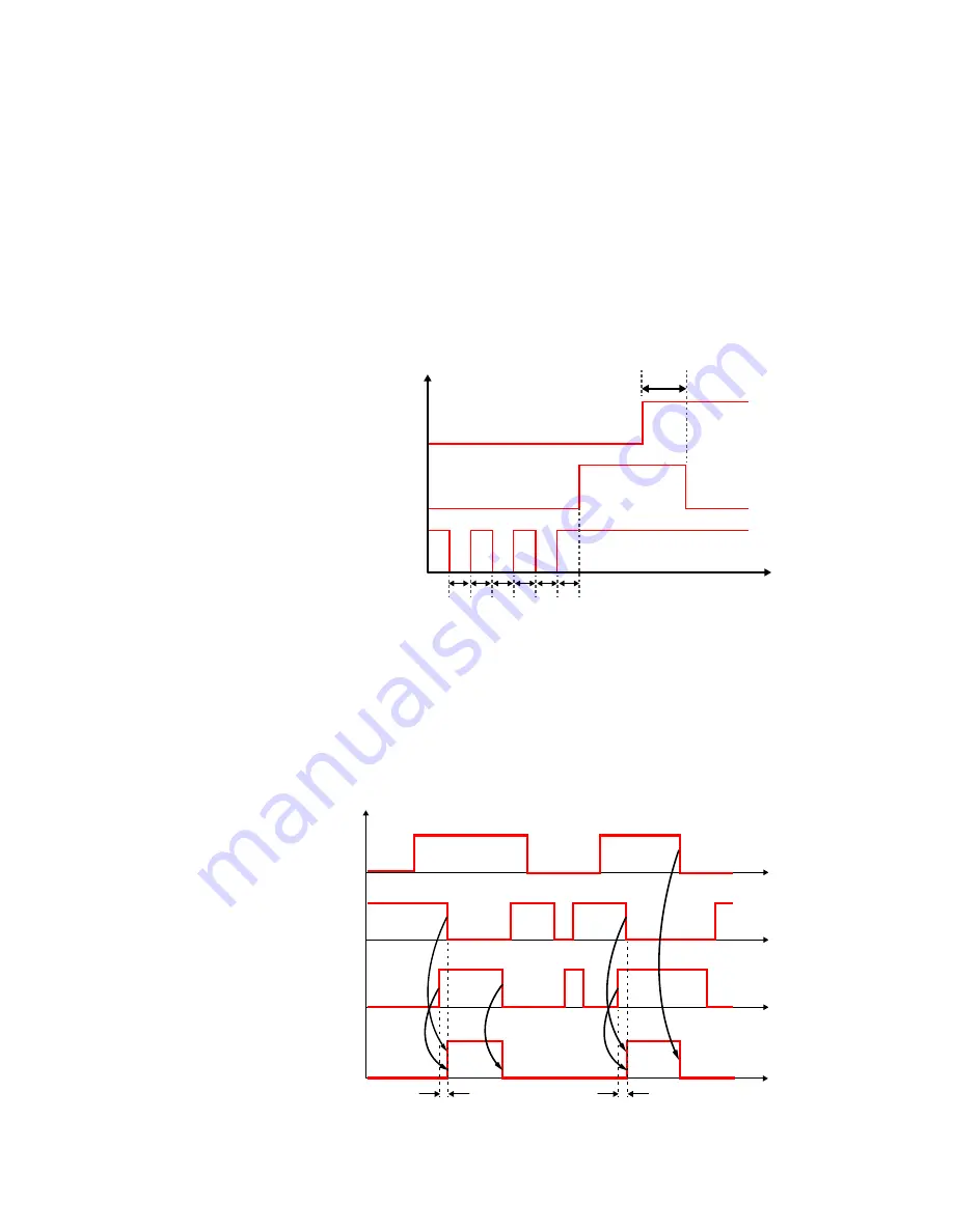
have one pin for an override. Thus the only option is the Single Line Pattern override input. The initiation of the override
function is not as simple as opening the override switch. The scanner must receiver a specific series of voltage signals to
start the override process. To force the scanners outputs on, the safety zone must be violated and at least one mute sensor
must be blocked (on). At this time, the override switch must be opened and closed three times, for less than one second
each time.
Figure 49. Mute dependent override timing diagram
2 s
<1s <1s <1s <1s <1s >1s
Safety Zone
Intercepted
Free
ON
Override Status
OFF
Released 24Vdc
Override Single Line Pattern
Pressed (0Vdc or floating)
When the override signal is accepted the display will show Override and the OSSD LED will be on green.
Mute Dependent Override with 12-pin or more models
—Other than being able to select the one terminal Single Line
Pattern override configuration, a configuration can also select a two input Level triggered or a two-input Edge triggered
override configuration. The difference between these two override processes is what happens to the override switches once
the override process starts.
Even during the override process, the safety logic will have priority. If the override is active, the OSSDs will still go to the off
state (STOP) if the non-muted/overridden safety areas (areas that do not have the override function selected) detect an
intrusion. The possibility of selection gives the system more flexibility, but it is obviously subject to a risk analysis by the user.
Level Triggered Pattern
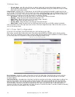
—The input sequence to be followed for activation is indicated by the following figure:
Figure 50. Level triggered pattern timing diagram
t < 400 ms
Override Conditions
OFF
ON
24Vdc
Override 2
0Vdc
24Vdc
Override 1
0Vdc
ON
Override Status
OFF
t < 400 ms
Edge Triggered Pattern
—The input sequence to be followed for activation is indicated by the following figure:
SX Safety Laser Scanner
www.bannerengineering.com - Tel: + 1 888 373 6767
71


