•
Override Status
—when the muting function is enabled, enabling the Override Status allows assigning an output
signal to indicate when the safety function has been manually deactivated (forcing the OSSDs on) to clear the safety
zone from a work cycle anomaly.
Output Signals
—assigning wires to output signals. The first OSSD pair is automatically assigned to specific pins and can
not be changed. The Multi In/Out pins can be assigned as inputs or outputs depending on the configuration settings. If one of
these pins is set as an output, it can not be used as an input. From the
Output Configuration
page, the Multi Out pins and
Multi In/Out pins can be assigned as follows (depending on configuration settings):
•
No Function
—If the pin is to be used as an input or not at all select no function at this time.
•
Warning x
—Assign the pin as either auxiliary warning output 1 or 2.
•
Muting Lamp
—Assign the pin as a mute lamp output if muting is selected.
•
Alarm x
—Assign the pin as either alarm output 1 or 2.
•
Override Status
—Assign the pin as a override lamp if override is enabled.
•
Safety Output
—Assign the pin as half of an OSSD output pair is more than one OSSD output pair is selected.
Click on the white
>
arrow in the upper right corner to move to the next configuration screen. Click on the white
<
arrow to
return to the previous screen.
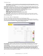
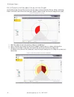
6.6.2 Zone Set Configuration
A Zone Set is the combination of a configured Safety Zone (SZ) and Warning Zone (WZ).
When active, a specific Zone Set has sole control of the safety outputs (OSSD1 and OSSD2) and the Warning auxiliary
output, if set in the configuration. This function is useful to change the safeguarding area in applications in which a hazard is
not continually present or in applications in which speed and stopping distances varies.
Figure 60. Zone Set Configuration screen
Zone Set Number
—Selects the number of Zone Sets to use for the configuration. The default value is one Zone Set (no
Area Switching). Add more Zone Sets using the up arrow. The maximum number of Zone Sets depends on model and
connector selected.
Input Delay Max (ms)
—Required when at least two Zone Sets are selected; sets the delay to apply between switching from
one Zone Set to another. The input delay allows waiting for the Area Switch inputs to stabilize from their transient states
before accepting the Zone Set. The Zone Set will not switch until the end of the selected time (the time starts when it sees
the first transition), otherwise the activation and deactivation of the inputs could put the device in undesired/invalid and
temporary switching zone input combinations and cause the device to enter the fault state. The minimum (default) input delay
value is 30 ms and can be increased in 30 ms increments.
SX Safety Laser Scanner
82
www.bannerengineering.com - Tel: + 1 888 373 6767


