The conditions for switching Zone Sets must be in accordance with a risk assessment. Machine stopping/braking distances,
scanner system response time (including interfacing devices), machine stop time and other factors that influence the Safety
Distance (minimum distance) and Stopping Distance calculations must be considered to safely use the Zone Set switchover
function.
In applications that incorporate Zone Set switchover, Minimum Distance D and Side Distance Z must be calculated
individually for all Zone Sets. Conditions to allow switching Zone Sets:
•
Only one Zone Set can be active after the switchover time; see the Zone Set logic in the configuration software.
•
Zone Set switchover is allowed even if there is an intrusion into the active Safety Zone (i.e. OSSDs are off).
•
The switchover must be made within the Max Input Delay time selected in the configuration software. The input delay
allows waiting for the Area Switching inputs to stabilize from their transient states before accepting the Zone Set
change. Otherwise the activation and deactivation (bouncing) of the inputs could put the device into undesired or
invalid and temporary switching zone input combinations and therefore cause the device to enter the fault state. The
minimum input delay (default) value is 30 ms. It can be increased in 30 ms increments.
In addition, factors dependent on the risk assessment that may affect the safety circuit integrity level include:
•
Analyze the means of selecting Zone Sets with respect to failure modes to ensure that an unintended switchover
does not occur.
•
Ensure that selecting/deselecting Zone Sets does not expose any individual to a hazard. Supplemental safeguarding
may be required.
Zone Set Configuration
1. On the
Zone Set Configuration
screen, set the
Zone Set No
.
Depending on the model and the other features used, you can use from 1 to 70 different Zone Sets by changing the
number shown to match the number of desired Zone Sets.
When increasing the number of Zone Sets, the warning 'To go on, Zones design will be modified' may display. Click
Ok
. The previous settings allow multiple Zone Sets. If a different warning displays, the previous settings must be
changed to use multiple Zone Sets.
2. Set the
Input Delay Max
(ms).
After more than one Zone Set is selected, this input field is displayed. This allows the setting of the delay applied
between switching from one Zone Set to the next. The input delay allows waiting for the Area Switching inputs to
stabilize from the transient states before accepting the Zone Set change. Otherwise the activation and deactivation of
the inputs could put the device in an undesired or invalid Zone Set state resulting in a potential unsafe or fault
condition. The minimum input delay (default) value is 30 ms. It can be increased in 30 ms increments.
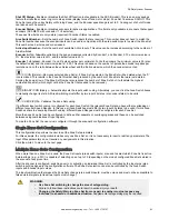
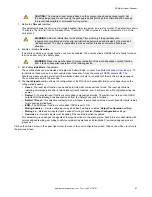
WARNING:
Set the
Input Delay Max
time as low as possible because the scanner will not react
to violations of the new Zone Set's Safety Zone during this Zone Set changeover time.
3. Set the
Zone
parameters.
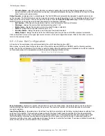
This parameter group allows editing the Area Switch input combinations depending on how many Zone Sets are
selected. The number of Area Switches (AS#) equal to the number of unassigned inputs will appear in the graphic.
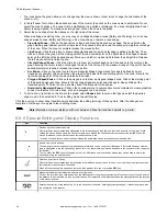
Manually set the input switch coding by clicking inside the Area Switch boxes for each Zone Set. To be valid, all Area
Switching must differ by two input bit states. It is possible to set the input switch coding with specific function buttons.
•
If the configuration includes only one Zone Set, it is not necessary to insert any parameters.
•
As more zone sets are added, more area switch inputs are needed (the maximum number of area switch inputs is
8 for 37 to 70 Zone Sets).
•
If two Zone Sets are selected, at least two pins must be assigned to the Area Switch function.
•
For the SX5-B and SX5-B6 models: If 3 to 6 Zone Sets are selected (in this case no other functions are available),
pins 1, 3 and 4 must be assigned to the Area Switch function.
•
For the SX5-B and SX5-B6 models: If 4 to 6 Zone Sets are selected, the ability to switch between Zone Sets is
limited. This limitation is to ensure that two Area Switch inputs must change to switch between Zone Sets. The
software does not obligate changing the Zone Sets sequentially (i.e. Zone Set 1, 2, 3, 4, etc in order), therefore
the user must verify that the selected passage from one Zone Set to another (in any order) guarantees that at
least two Area Switch inputs change signal levels.
SX Safety Laser Scanner
84
www.bannerengineering.com - Tel: + 1 888 373 6767


