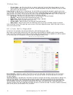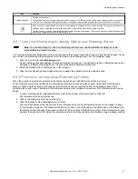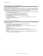
6.6.3 Input Configuration
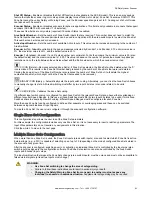
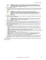
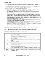
Figure 63. Input Configuration screen
For each OSSD pair configured, define the following parameters under
Safety Zone x
in the
Input Function
section.
1. Configure the
Restart Mode
.
•
Automatic
—The scanner automatically returns the OSSD pair to the On-State after all detected objects are
removed from the Safety Zone and the configured Recovery Time elapses.
•
Manual
—The scanner returns the OSSD pair to the On-State after all detected objects are removed from the
Safety Zone and a manual Restart switch (reset push-button) is pressed for at least 500 ms, but no longer than
4.5 seconds.
2. Define the
Recover Time
.
This parameter is only configured for Automatic Restart Mode. The Recover Time is the time between the object
removal from the Safety Zone and the OSSDs going to the On-State. Select the time to elapse before the OSSD pair
returns to the On-State. The minimum time is 200 ms. This can be increased to 60,000 ms in 1 ms increments.
Default: 200 ms
3. Select EDM to enable the External Device Monitoring (EDM) function.
4. Configure
EDM Delay Time
(ms).
The time delay provided for the monitored device to go from its open state to its closed state when the OSSD outputs
turn off can be set from 200 to 1000 ms. Default setting is 350 ms.
5. Define the
Muting Type
.
If muting is not selected, this option is grayed out. The Muting function can be used in two different configurations.
•
Bidirectional
—Used when objects can pass through the Safety Zone from either direction; requires two or four
muting sensors be connected to the scanner inputs
•
Unidirectional
—Used when objects can pass through the Safety Zone from only one direction (out of the
hazardous area); requires two muting sensors be connected to the scanner inputs
•
M coeff.
—If Unidirectional Muting is selected, the M coeff is displayed. The M coefficient is the time delay
multiplier that times out the Muting function after a mute sensor clears (typically mute 1). The M coeff can be set
from 2 to 16. This is the multiplier of the activation delay between the initiation of the two muting sensors. The
maximum amount of time that the system will stay muted after the clearing of mute 1 is M Coeff × Max Inputs
Delay (actual elapsed time between the activation of mute 1 and mute 2).
6. Define the
Max Inputs Delay
(seconds).
The maximum allowable time delay between activation of mute 1 and mute 2. This parameter can be set from 1 to 16
seconds with the default being 4 seconds. If muting is disabled, this field cannot be adjusted.
SX Safety Laser Scanner
86
www.bannerengineering.com - Tel: + 1 888 373 6767


