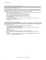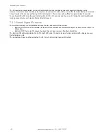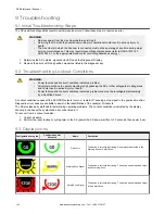
Icon
Function
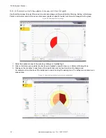
{upside-down box}
Flips the scanner over.
The standard view has the top of the scanner at the center point. Clicking the Upside Down box puts the bottom of the scanner
in the center of the graph. Nothing physically has changed but this allows the graph to match the orientation of the scanner.
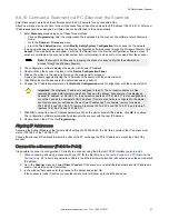
When a scanner is attached and any form of Live Monitoring is engaged, this icon can be selected. This causes the scanner to
show any areas of high light input (a reflective surface or light source is being seen by the scanner).
This can assist in removing potential interference sources from the environment. This icon can be used in the Monitoring mode
and in Zone configuration when Live Monitoring is on.
6.6.7 Use Live Monitoring to Assign Safety and Warning Zones
Note:
The Live Monitoring On, Use Live Monitoring to Draw Zone, and Show Reflective Object icons are
only available if a scanner is online.
You may use the Live Monitoring function to outline the space the scanner is guarding, then go back and use shapes. Or you
can use the Live Monitoring Area Assignment to set the fields in the detected area, up to the maximum range.
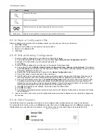
1. Click the icon to enter
Live Monitoring
mode.
Live Monitoring scans and displays the area surrounding the scanner. The white area is free of obstacles and can be
assigned to a Safety or Warning Zone. The gray areas contain detected obstructions.
2. Select the Safety Zone or Warning Zone in the left pane.
3. Click the Live Monitoring Area Assignment icon to assign the defined area to the selected zone.
6.6.8 Protect a Vertical Area (Reference Points)
When the scanner is mounted to protect a vertical area (up and down), add Reference Points to an edge.
These reference points are positions where something will always be sensed by the scanner (the surface will always be
present). These points are used by the scanner to ensure that it has not come loose from its mounting surface and is
protecting the correct area. A minimum of three reference points must be added. A maximum of 15 reference points can be
added.
1. To add a reference point, highlight Reference Point at the bottom of the list of Zones on the left.
The reference point icon becomes live.
2. Click on the Reference Point icon on the right.
3. Click the locations of the desired Reference Points.
The maximum distance from the scanner that a reference point can be configured is based on the maximum range
for the selected resolution. The Reference Points do not have to be at the edge of the Safety Zone. If the distance to
the reference point changes, the scanner will turn off. So even if the Safety Zone is muted, if the reference point gets
blocked, the outputs turn off. Select the reference points so that they should not be blocked during a muting evolution.
SX Safety Laser Scanner
www.bannerengineering.com - Tel: + 1 888 373 6767
91


