11. Click on the right arrow to advance to the next screen.
The Detection
Configuration
screen displays. This screen is for the Detection
Configuration
of the Safety Zone and, if
included, the Warning Zone(s). Make no changes to the default settings on this screen for demo kit
configuration
1.
The Number of Scans can be set from 2 to as high as 16 if there are insects or other
floating
objects that could trip the
scanner outputs. Increasing the number of scans increases the response time needed to stop the hazard.
The choice of Detection Capability refers to the resolution at maximum range. For most horizontal detection applications, a
resolution of 70 mm will reach a safety zone distance of 5.5 meters. If 40 mm is selected, the maximum safety range is 3
meters, which may be adequate for vertical apps. The same settings can be selected for the Warning Zone(s), resulting in a
range of either 40 meters or 22 meters.
The Dust Filter level selection defaults to low. The Low Dust Filter level setting is used in cleaner environments. The High
Dust Filter Level is used in extemely dirty environments to prevent
floating
particles from being detected. A Medium Dust
Filter setting is for conditions between Low and High. Raising the dust
filter
level increases the safety distance under
certain lighting conditions.
12. Click on the right arrow to advance to the next screen.
The Zones
Configuration
screen displays.
The Zones
Configuration
screen displays the scanner viewed from above. Use this screen to design the shape and
extended distance needed for the correct Safety Zone protection and any Warning Zone(s) needed for a
specific
configuration.
In the center is the Area Graph. On the left is a list of zones that can be
configured.
On the right are the various
configuration
icons. To
configure
Demo
Configuration
1, a circular Safety Zone and Warning Zone will be added.
13. Under
Configuration
> ZoneSet > Zone1, click on Safety to select it.
14. Click on the circle icon tool on the right.
15. Position the mouse pointer over the scanner image. Click and hold down the left button to drag the image to the left to
create a red Safety Zone circle. Release the mouse button after you are close to X=200mm.
To delete the shape and create another, move your mouse over the shape. Right-click and select the shape name. From
the editing choices, click delete.
If no icons display, click on the small arrow at the top right to view all icons. If no
Configuration
for Zone sets are visible,
click on the arrow at the top left of the page.
16. To create a Warning Zone, click to highlight the Warning 1. Select the circle icon and drag the mouse to the left until you
are close to X=400 mm. Use the + and - icons to change the size of the image if necessary.
17. To view the Safety Zone and the Warning Zone, select both.
The Reference Point is not used for this
configuration.
A minimum of three assigned reference points are needed for
vertical applications when surfaces are monitored to ensure the scanner doesn't shift from its mounted position.
The
configuration
up to this point (steps 1-17) may be performed without an attached scanner.
18. To transfer the completed
configuration
to the attached scanner, click on the Programming function.
If this is your
first
attempt to program the scanner since the software was launched, the software performs a Discovery
function as it forms a communications link to the attached SX5-B.
19. Double-click on the SX5-B image (with IP address) on the left side, then click on the right arrow to advance to the next
screen.
20. In the
Configuration
Upload window, click Load.
21. If the program was successfully validated, click OK. If an error message appears, resolve the issue.
22. When the system asks for a password, enter
admin
and click OK. Click OK for the Off-Duty warning.
The software begins to upload the
configuration
files
to the scanner. Transferring
files
to or from the scanner may take up
to 60 seconds to complete. During and after the upload, the SX5-B display updates with status information on the
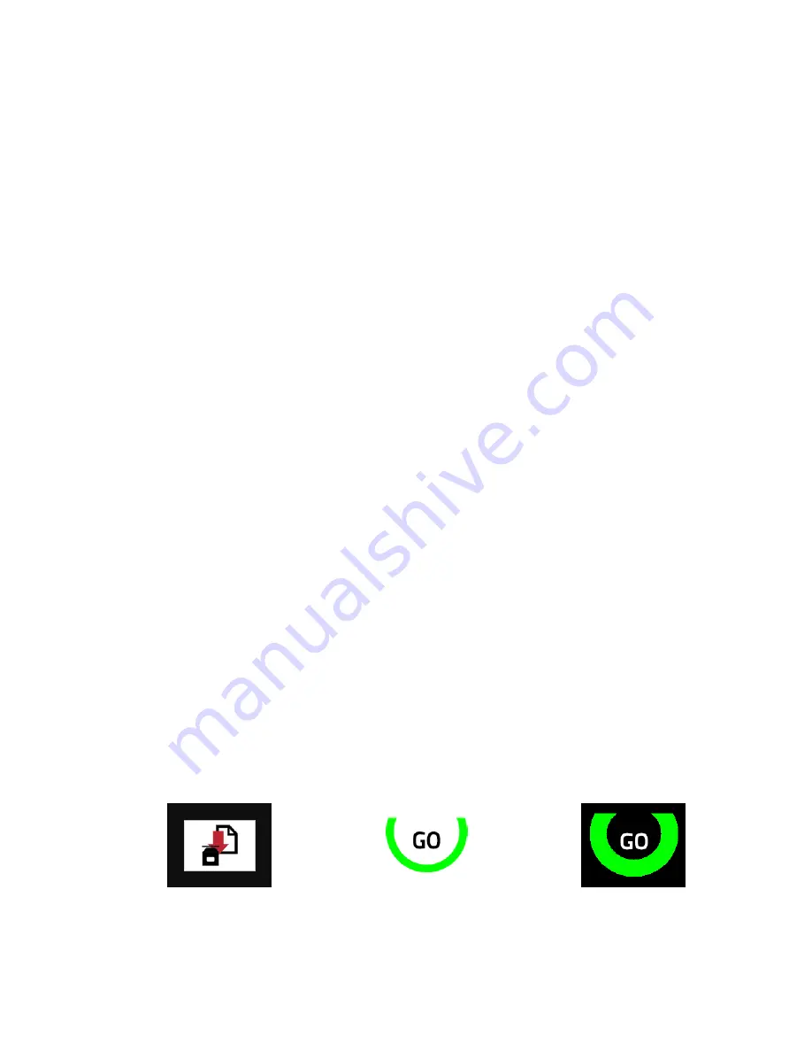
progress. When the upload is complete, the display show inverted colors to indicate the scanner is still in a pre-acceptance
stage. This stage allows you to test in Monitoring mode before you accept the
configuration.
23. After transferring the
configuration
file
to the scanner, click Accept in the Validation window. Wait for
finalizing
to be
completed. The SX5-B display inverts the colors to show a black color background.
The
configuration
file
is loading
Before validation
After validation
A summary document is available, from this screen, that contains information about the
configuration
file.
The summary
document can be printed or saved to a PDF.
24. To view the scanner's response with the programmed settings, click on the Monitoring function.
SX5 Safety Scanner Demo Kit Setup Instructions
4
www.bannerengineering.com - Tel: + 1 888 373 6767
P/N 209666 Rev. A


