


TCNM-ACBB1 Installation Manual
2
p/n 174477 Rev. A
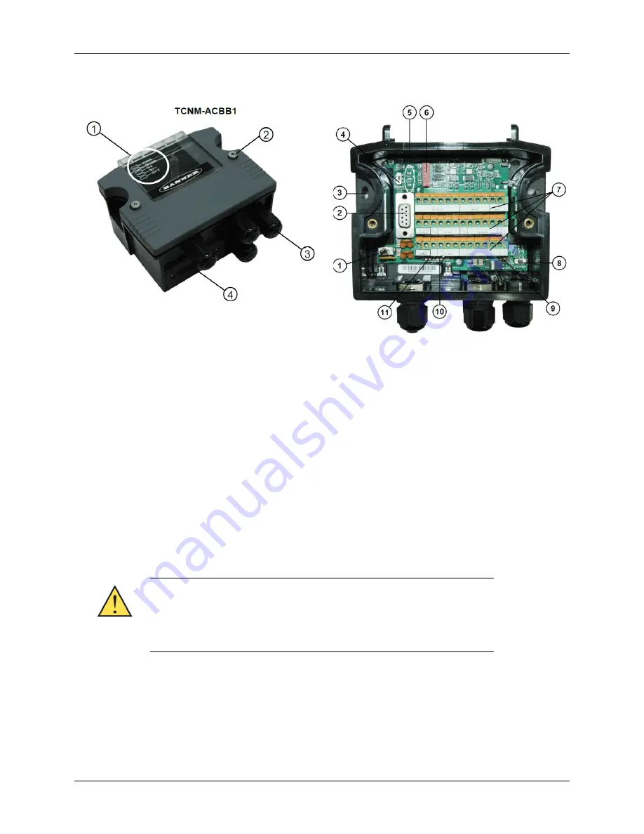
General View
1 – Indicator LEDs
2 – Cover screws (2)
3 – Compression connectors (4)
4 – 25-pin device connector
1 – Power switch (on/off)
2 – Auxiliary port connector
3 – Mounting holes (2)
4 – ID-NET termination resistance switch
5 – Indicator LEDs
6 – Backup module connector
7 – Spring clamp terminal blocks
8 – RS485 termination resistance switch
9 – Power source selector
10 – Shield to protection earth selector
11 – Chassis grounding selector
Safety Precautions
ATTENTION: READ THIS INFORMATION BEFORE INSTALLING THE PRODUCT POWER SUPPLY
This product is intended to be installed by Qualified Personnel only. This device is intended to be
supplied by a UL Listed NEC Class 2 power source.
Total power consumption is given by adding the TCNM-ACBB1 power
consumption to that of all the devices powered through the TCNM-
ACBB1 (reading device, P.S.,I/O). Refer to the manual of the connected
devices for details about minimum/maximum supply voltage and power
consumption.
Each TCNM-ACBB1 supports only 1 single reading system accessories.
Supposed Reading Device Models
The TCNM-ACBB1 can be connected to the following readers using the 25-pin connector.
•
TCNM-AD
•
TCNM-EX


