background image

TCNM-ACBB1 Installation Manual 


p/n 174477 Rev. A 

Electrical Connections and Setup 

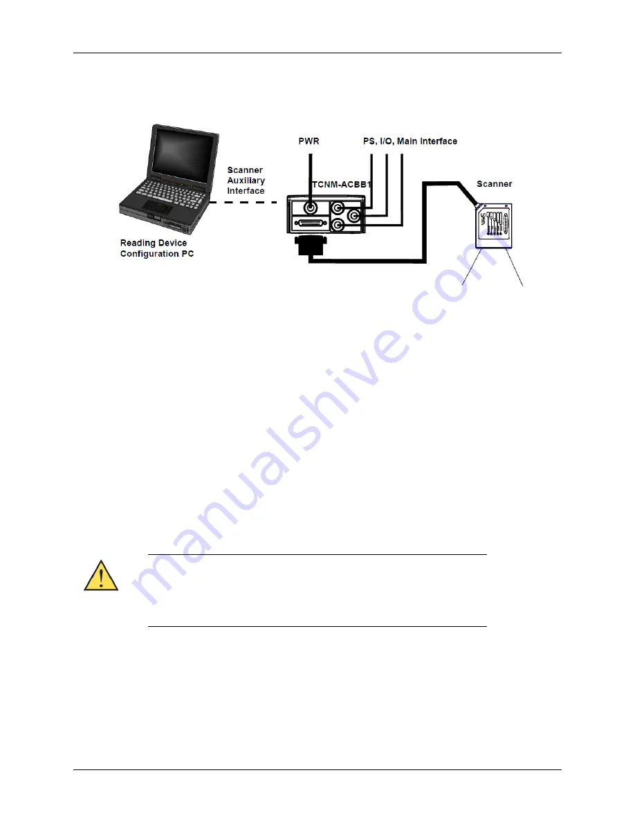
The following figure shows a typical layout. 


The dotted line in the figure refers to an optional (temporary) hardware configuration in which a 

portable PC can be quickly connected to the TCNM-ACBB1 (and consequently to the reading device 

auxiliary interface) through the internal 9-pin connector. This allows monitoring of the data transmitted 

by the reading device or configuration through the utility program (see the reading device Installation 

Manual for more details). The reading device auxiliary interface signals are also available on the internal 

spring clamp connectors. 
After making system cabling and switch settings, connect the reading device to the 25-pin connector on 

the TCNM-ACBB1 housing. 
Switch ON the TCNM-ACBB1 power switch. The Power LED turns on (blue) when the power connection 

has the correct polarity. The Power LED turns on (red) in case of wrong polarity. 
After system functioning has been verified, close the TCNM-ACBB1 using the two cover screws. 

Power Supply 

Power is supplied to the TCNM-ACBB1 through the Vdc and GND pins provided on the spring clamp 

connector. 
The power switch switches the power supply ON or OFF for both the TCNM-ACBB1 and the connected 

reading device. 

The power switch does not control power to the Vdc/GND, +V/-V spring 

clamps, therefore any devices connected to these signals (i.e. external 

trigger, encoder, etc.), are live and are not protected from polarity 

inversion. Disconnect the power supply when working inside the TCNM-

ACBB1. 


Summary of Contents for TCNM-ACBB1

Page 1: ...through spring clamp terminal blocks inside the TCNM ACBB1 while the reading device is connected to the TCNM ACBB1through a 25 pin connector on the housing A 9 pin connector placed inside the TCNM AC...

Page 2: ...READ THIS INFORMATION BEFORE INSTALLING THE PRODUCT POWER SUPPLY This product is intended to be installed by Qualified Personnel only This device is intended to be supplied by a UL Listed NEC Class 2...

Page 3: ...ous wooden or plastic surfaces using the two self threading screws 3 9 x 45 mm and washers provided in the package Mounting to other surfaces such as concrete walls or metallic panels requires user su...

Page 4: ...tem cabling and switch settings connect the reading device to the 25 pin connector on the TCNM ACBB1 housing Switch ON the TCNM ACBB1 power switch The Power LED turns on blue when the power connection...

Page 5: ...ork Cable Shield Shield to Filtered Earth through the jumper default setting System Wiring The connection and wiring procedure for TCNM ACBB1 is described as follows 1 Open the TCNM ACBB1 by unscrewin...

Page 6: ...on Earth Ground External Trigger Input V Power Source External Trigger I1A External Trigger A polarity insensitive I1B External Trigger B polarity insensitive V Power Reference External Trigger Generi...

Page 7: ...hrough the 25 pin connector This is useful for example to pass power to connected accessories such as Encoder See the relative reading device Reference Manual for details To power TCNM ACBB1 from the...

Page 8: ...ctor pins are listed in the following table TCNM ACBB1 9 pin Female Connector Pinout Pin Name Function 2 TX Auxiliary RS232 3 RX Auxiliary RS232 5 SGND Auxiliary Reference Ground 1 4 6 7 8 9 N C Netwo...

Page 9: ...all the other devices disable this resistor OFF TCNM ACBB1 Backup and Restore Module Accessory The TCNM ACBB1 Backup and Restore Module separate accessory provides configuration parameter backup It ca...

Page 10: ...hrough TCNMACBB1 connected to V V they are not protected from polarity inversion The remaining four LEDs signal activity on the relative I O lines Their meaning depends on the software configuration o...

Page 11: ...to 10 Hz 1 5 mm 13 to 55 Hz 2 g 70 to 200 Hz Shock Resistance EN 60068 2 27 30 g 11 ms 3 shocks on each axis Protection Class EN 60529 IP65 when compression connectors and reading device are correctl...

Reviews: