TCNM-ACBB1 Installation Manual
6
p/n 174477 Rev. A
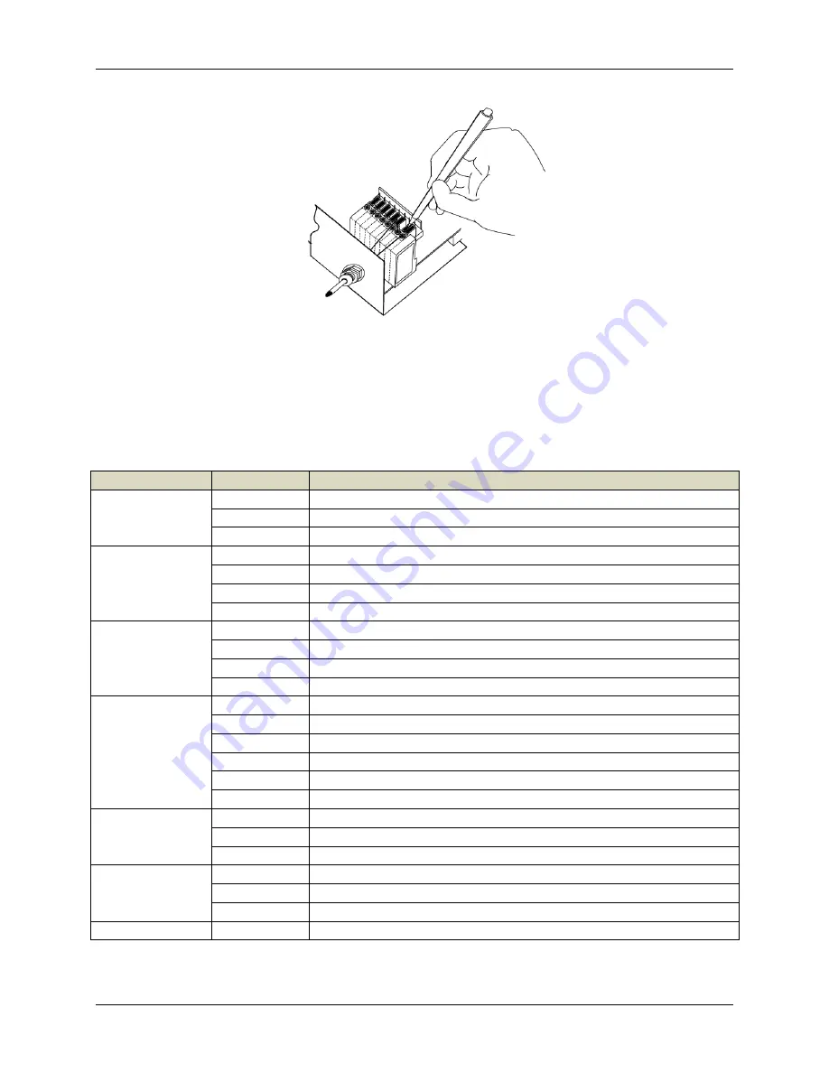
System Cable Connections
Use flexible stranded wire and meet the following specifications.
All positions: 24 - 16 AWG 0.2 - 1.5 mm²
The TCNM-ACBB1 spring clamp connector pinouts are indicated in the pinout table.
Refer to the reading device installation manual for signal details.
Pinouts
Group
Name
Function
Input Power
Vdc
Power Supply Input V
GND
Power Supply Input Voltage -
Earth
Protection Earth Ground
External Trigger
Input
V+
Power Source – External Trigger
I1A
External Trigger A (polarity insensitive)
I1B
External Trigger B (polarity insensitive)
-V
Power Reference – External Trigger
Generic Input
+V
Power Source – Inputs
I2A
Input 2 A (polarity insensitive)
I2B
Input 2 B (polarity insensitive)
-V
Power Reference – Inputs
Outputs
+V
Power Source – Outputs
-V
Power Reference – Outputs
O1+
Output 1 +
O1-
Output 1 -
O2+
Output 2 +
O2-
Output 2 -
Auxiliary Interface
TX
Auxiliary Interface TX
RX
Auxiliary Interface RX
SGND
Auxiliary Interface Reference
ID-NET
REF
Network Reference
ID+
ID-NET N
ID-
ID-NET Network -
Network
Shield
Network Shield Cable


