background image

TCNM-ACBB1 Installation Manual 


p/n 174477 Rev. A 

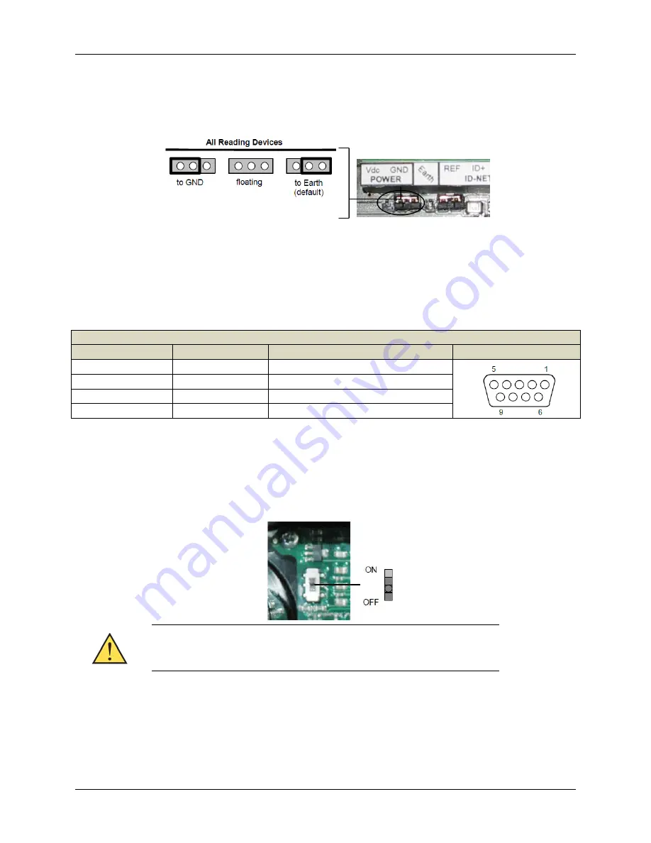
For all reading devices , the chassis can alternatively be connected to the power supply ground signal 

(GND) or it can be left floating (remove the jumper). 

Chassis Grounding 


9-Pin Reading Device Auxiliary Serial Interface 

Use the reading device auxiliary serial interface available on the internal TCNM-ACBB1 9-pin connector 

for configuration or data monitoring.  
Connect the device to a PC or Laptop using a straight through cable or a USB-RS232 converter. The 

connector pins are listed in the following table. 

TCNM-ACBB1 9-pin Female Connector Pinout 

Pin 

Name 

Function 


TX 

Auxiliary RS232 


RX 

Auxiliary RS232 

SGND 

Auxiliary Reference Ground 

1, 4, 6, 7, 8, 9 


N.C. 

Network Bus Termination 

The ID-NET termination resistance switch enables or disables the insertion of the bus termination 

resistor for ID-NET network applications. 

ID-NET Termination Resistance Switch 


In ID-NET network applications, enable the termination resistor (ON) on 

the first and last devices of the chain. On all the other devices, disable 

this resistor (OFF). 

 
The RS485 HD termination resistance switch enables or disables the insertion of the bus termination 

resistor for RS485 Half Duplex Multidrop applications. 

Summary of Contents for TCNM-ACBB1

Page 1: ...through spring clamp terminal blocks inside the TCNM ACBB1 while the reading device is connected to the TCNM ACBB1through a 25 pin connector on the housing A 9 pin connector placed inside the TCNM AC...

Page 2: ...READ THIS INFORMATION BEFORE INSTALLING THE PRODUCT POWER SUPPLY This product is intended to be installed by Qualified Personnel only This device is intended to be supplied by a UL Listed NEC Class 2...

Page 3: ...ous wooden or plastic surfaces using the two self threading screws 3 9 x 45 mm and washers provided in the package Mounting to other surfaces such as concrete walls or metallic panels requires user su...

Page 4: ...tem cabling and switch settings connect the reading device to the 25 pin connector on the TCNM ACBB1 housing Switch ON the TCNM ACBB1 power switch The Power LED turns on blue when the power connection...

Page 5: ...ork Cable Shield Shield to Filtered Earth through the jumper default setting System Wiring The connection and wiring procedure for TCNM ACBB1 is described as follows 1 Open the TCNM ACBB1 by unscrewin...

Page 6: ...on Earth Ground External Trigger Input V Power Source External Trigger I1A External Trigger A polarity insensitive I1B External Trigger B polarity insensitive V Power Reference External Trigger Generi...

Page 7: ...hrough the 25 pin connector This is useful for example to pass power to connected accessories such as Encoder See the relative reading device Reference Manual for details To power TCNM ACBB1 from the...

Page 8: ...ctor pins are listed in the following table TCNM ACBB1 9 pin Female Connector Pinout Pin Name Function 2 TX Auxiliary RS232 3 RX Auxiliary RS232 5 SGND Auxiliary Reference Ground 1 4 6 7 8 9 N C Netwo...

Page 9: ...all the other devices disable this resistor OFF TCNM ACBB1 Backup and Restore Module Accessory The TCNM ACBB1 Backup and Restore Module separate accessory provides configuration parameter backup It ca...

Page 10: ...hrough TCNMACBB1 connected to V V they are not protected from polarity inversion The remaining four LEDs signal activity on the relative I O lines Their meaning depends on the software configuration o...

Page 11: ...to 10 Hz 1 5 mm 13 to 55 Hz 2 g 70 to 200 Hz Shock Resistance EN 60068 2 27 30 g 11 ms 3 shocks on each axis Protection Class EN 60529 IP65 when compression connectors and reading device are correctl...

Reviews: