background image

Original Instructions
December 19, 2023

p/n: 237795 Rev. A

TL50 Basic Wireless Andon Tower Light 
Instruction Manual


Features

Multi-Color and Audible Andon Indicators


Rugged, cost-effective, and easy-to-install Andon indicators 
Illuminated tower light segments and Andon box indicators provide easy-to-see status 

Four available colors: blue, green, yellow, and red
Integral four capacitive touch button controller with status LEDs
Steady or flashing status capability
300 mm pre-assembled stand-off pipe length

Two wireless ISM radio options: 900 MHz and 2.4 GHz

Models

Model

LCA130T Controller Radio Frequency

Tower Light Description

LCA130T4DXN2-TL50BGYR300Q

2.4 GHz

TL50 Basic Andon Tower Light (Blue, Green, Yellow, Red)

LCA130T4DXN9-TL50BGYR300Q

900 MHz

TL50 Basic Andon Tower Light (Blue, Green, Yellow, Red)

TL50-LCA130T Switch Diagrams

The control box status LED mimics the tower light status in color and animation.

Tap one of the buttons to turn the corresponding status LED on or off. Hold the button to activate the flashing function.

4

3

2

1

LED Key:

1 = Blue
2 = Green
3 = Yellow
4 = Red

Input Pinout - All Models

4-Pin M12 Male Connector

Pin

Wire Color

Wiring Description

1

4

3

2

1

Brown (bn)

18 V DC to 30 V DC 

2

White (wh)

Use to configure with the Pro Editor Configuration software

3

Blue (bu)

DC common (GND)

4

Black (bk)

Not Used

Configuration Instructions

LCA130T DIP Switches

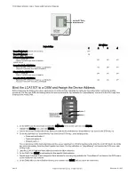
Before applying power to the device, set the radio's DIP switches.

© Banner Engineering Corp.

Summary of Contents for TL50

Page 1: ...on LCA130T4DXN2 TL50BGYR300Q 2 4 GHz TL50 Basic Andon Tower Light Blue Green Yellow Red LCA130T4DXN9 TL50BGYR300Q 900 MHz TL50 Basic Andon Tower Light Blue Green Yellow Red TL50 LCA130T Switch Diagram...

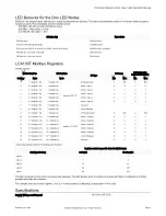
Page 2: ...n the DITA map from binding to the wrong DXM Button 2 Button 1 On the DXM Use the arrow keys to select the ISM Radio menu on the LCD and click ENTER 1 Highlight the Binding menu and click ENTER 2 Use...

Page 3: ...ode x 8 Button 3 Input 3 0 2 0 2 5 5 Node x 16 4 Node x 8 Button 4 Input 4 0 2 0 2 6 6 Node x 16 5 Node x 8 Button 5 Input 5 0 2 0 2 7 7 Node x 16 6 Node x 8 Reserved 8 8 Node x 16 7 Node x 8 Device M...

Page 4: ...s Overcurrent protection is required to be provided by end product application per the supplied table Overcurrent protection may be provided with external fusing or via Current Limiting Class 2 Power...

Page 5: ...installed and used in accordance with the instruction manual may cause harmful interference to radio communications Operation of this equipment in a residential area is likely to cause harmful interf...

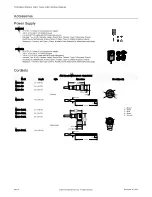
Page 6: ...input 3 5 m 11 5 ft PVC cable with M12 quick disconnect Includes Type A US Canada Japan Puerto Rico Taiwan Type C Germany France South Korea Netherlands Poland Spain Turkey Type G United Kingdom Irel...

Page 7: ...R A PARTICULAR PURPOSE AND WHETHER ARISING UNDER COURSE OF PERFORMANCE COURSE OF DEALING OR TRADE USAGE This Warranty is exclusive and limited to repair or at the discretion of Banner Engineering Corp...

Reviews: