Specifications
Power
12 V dc to 30 V dc (24 V dc ± 10% if a Banner light source is powered by the sensor)
Current: 400 mA maximum (exclusive of load and lights)
Use only with a suitable Class 2 power supply, or current limiting power supply rated
12 V dc to 30 V dc, 1 A
Supply Protection Circuitry
Protected against reverse polarity and transient overvoltages
Discrete I/O
1 Trigger IN
5 Programmable I/O
Output Configuration
Optically isolated
Output Rating
Output Resistance: < 2 Ω
Strobe Output Resistance: < 13 Ω
Programmable Output: 100 mA
External Strobe Output: 100 mA
Off-State Leakage Current: < 100 µA
External Light Maximum Current Draw
350 mA
Exposure Time
0.01 ms to 500 ms
Memory
Device Settings and Inspection Storage Memory: 500 MB
Number of inspection files: 999
Acquisition
256 grayscale levels
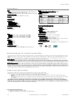
Model
Frames Per Second4
Image Size
VE200G1A
60 fps, maximum
752 × 480 px
VE201G1A
60 fps, maximum
1280 × 1024 px
VE202G*A
50 fps, maximum
1600 × 1200 px
VE205G1A
22 fps, maximum
2592 × 2048 px
Torque—Tapped Holes for Mounting Screws
8 lbf·in (0.9 N·m) maximum torque
Construction
Housing: Aluminum
Display Label: Polyester
Connections
Ethernet: M12, 8-pin or 4-pin D-code Euro-style female
Light Connector: M8, 3-pin Pico-style female
Power, Discrete I/O: M12, 12-pin Euro-style male
Imager
VE200G1A: 6.9 mm × 5.5 mm, 8.7 mm diagonal (1/1.8-inch CMOS)
VE201G1A: 6.9 mm × 5.5 mm, 8.7 mm diagonal (1/1.8-inch CMOS)
VE202G*A: 7.2 mm × 5.4 mm, 9.0 mm diagonal (1/1.8-inch CMOS)
VE205G1A: 12.4 mm × 9.8 mm, 15.9 mm diagonal (1-inch CMOS)
Lens
C-mount
Pixel Size
VE200G1A: 5.3 µm
VE201G1A: 5.3 µm
VE202G*A: 4.5 µm
VE205G1A: 4.8 µm
Communication
10/100/10005 Mbps Ethernet
Communication Protocols
Ethernet/IP
™
, Modbus/TCP, PCCC, PROFINET
®
, TCP/IP, FTP, and RS-232
Environmental Rating
IEC IP67 with an optional sealed lens cover properly installed
Operating Conditions
Operating Temperature: 0 °C to +50 °C (+32 °F to +122 °F)
95% maximum relative humidity (non-condensing)
Stable Ambient Lighting: No large, quick changes in light level; no direct or reflected
sunlight
Storage Temperature: –30 °C to +70 °C (–22 °F to +158 °F)
Vibration and Mechanical Shock
Meets EN 60947-5-2: 30 G Shock per IEC 60068-2-27; 1 mm amplitude from 10 - 60
Hz per IEC 60068-2-6
Certifications
Information
Technology
Equipment
E365235
Banner Engineering Corp. Software Copyright Notice
This software is protected by copyright, trade secret, and other intellectual property laws. You are only granted the right to use the software and only for the purposes described by Banner. Banner reserves all
other rights in this software. For so long as you have obtained an authorized copy of this software directly from Banner, Banner grants you a limited, nonexclusive, nontransferable right and license to use this
software.
You agree not to use, nor permit any third party to use, this software or content in a manner that violates any applicable law, regulation or terms of use under this Agreement. You agree that you will not
reproduce, modify, copy, deconstruct, sell, trade or resell this software or make it available to any file-sharing or application hosting service.
Disclaimer of Warranties. Your use of this software is entirely at your own risk, except as described in this agreement. This software is provided "AS-IS." To the maximum extent permitted by applicable law,
Banner, it affiliates, and its channel partners disclaim all warranties, expressed or implied, including any warranty that the software is fit for a particular purpose, title, merchantability, data loss, non-interference
with or non-infringement of any intellectual property rights, or the accuracy, reliability, quality or content in or linked to the services. Banner and its affiliates and channel partners do not warrant that the services
are secure, free from bugs, viruses, interruption, errors, theft or destruction. If the exclusions for implied warranties do not apply to you, any implied warranties are limited to 60 days from the date of first use of
this software.
Limitation of Liability and Indemnity. Banner, its affiliates and channel partners are not liable for indirect, special, incidental, punitive or consequential damages, damages relating to corruption, security, loss or
theft of data, viruses, spyware, loss of business, revenue, profits, or investment, or use of software or hardware that does not meet Banner minimum systems requirements. The above limitations apply even if
Banner and its affiliates and channel partners have been advised of the possibility of such damages. This Agreement sets forth the entire liability of Banner, its affiliates and your exclusive remedy with respect to
the software use. You agree to indemnify and hold Banner and its affiliates and channel partners harmless from any and all claims, liability and expenses, including reasonable attorney's fees and costs, arising
out of your use of the Services or breach of this Agreement (collectively referred to as "Claims"). Banner reserves the right at its sole discretion and at its own expense, to assume the exclusive defense and
control of any Claims. You agree to reasonably cooperate as requested by Banner in defense of any Claims.
Additional Copyright Information
The Vision Manager software includes code that is copyright (c) 1985, 1989 Regents of the University of California. All rights reserved.
Redistribution and use in source and binary forms, with or without modification, are permitted provided that the following conditions are met:
1.
Redistributions of source code must retain the above copyright notice, this list of conditions and the following disclaimer.
2.
Redistributions in binary form must reproduce the above copyright notice, this list of conditions and the following disclaimer in the documentation and/or other materials provided with the
distribution.
3.
All advertising materials mentioning features or use of this software must display the following acknowledgement: This product includes software developed by the University of California, Berkeley
and its contributors.
4.
Neither the name of the University nor the names of its contributors may be used to endorse or promote products derived from this software without specific prior written permission.
THIS SOFTWARE IS PROVIDED BY THE REGENTS AND CONTRIBUTORS ``AS IS'' AND ANY EXPRESS OR IMPLIED WARRANTIES, INCLUDING, BUT NOT LIMITED TO, THE IMPLIED WARRANTIES OF
MERCHANTABILITY AND FITNESS FOR A PARTICULAR PURPOSE ARE DISCLAIMED. IN NO EVENT SHALL THE REGENTS OR CONTRIBUTORS BE LIABLE FOR ANY DIRECT, INDIRECT, INCIDENTAL,
SPECIAL, EXEMPLARY, OR CONSEQUENTIAL DAMAGES (INCLUDING, BUT NOT LIMITED TO, PROCUREMENT OF SUBSTITUTE GOODS OR SERVICES; LOSS OF USE, DATA, OR PROFITS; OR BUSINESS
INTERRUPTION) HOWEVER CAUSED AND ON ANY THEORY OF LIABILITY, WHETHER IN CONTRACT, STRICT LIABILITY, OR TORT (INCLUDING NEGLIGENCE OR OTHERWISE) ARISING IN ANY WAY OUT
OF THE USE OF THIS SOFTWARE, EVEN IF ADVISED OF THE POSSIBILITY OF SUCH DAMAGE.
4 This value can vary based on inspection settings.
5 1000 Mbps communication speed not available on 4-pin Ethernet models
VE Series Smart Camera
10
www.bannerengineering.com - Tel: +1-763-544-3164
P/N 191667 Rev. G