

Display
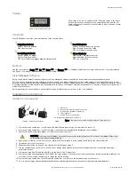
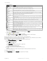
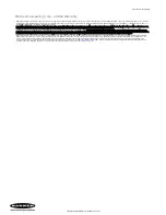
Figure 2. Display with Home Screen
The display is a 2-line, 8-character LCD. The main screen is the Home
Screen, which shows the name of the current inspection and the slot
number (inspection location). Use the display to view or change several
sensor settings.
Indicators
Four LED indicators provide ongoing indication of the sensing status.
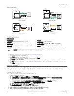
Power/Error Indicator
Green = Normal operation
Red = System error
Ready/Trigger Indicator
Green = Ready for trigger
Yellow = Trigger is active
OFF = Not ready for a trigger, triggers will be missed
Pass/Fail Indicator
Green = Previous inspection passed
Red = Previous inspection failed
OFF = No trigger since power up
Ethernet Indicator
Amber solid = Ethernet connection
Amber flashing = Ethernet activity
OFF = no connection
Buttons
Use the sensor buttons Down
, Up
, Enter
, and Escape
to configure several sensor settings and to access sensor information.
See
on page 9 for additional information on using the buttons.
Vision Manager
Software
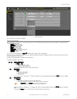
Set up the VE Series Smart Camera using the free Vision Manager Software, available for download at
This easy-to-use image processing software provides a variety of tools and capabilities to solve a wide range of vision applications such as item
detection, part positioning, feature measurement and flaw analysis. Run-time editing allows you to make changes to an inspection while the sensor
is running, reducing costly downtime. Vision Manager also includes a full software emulator, allowing users to develop or troubleshoot inspections
offline, without a sensor.
Password-protected user profiles are also available to enable different levels of access to the tools and data.
Installation Instructions
Install the Accessories
1
2
3
5
4
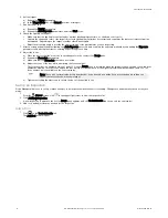
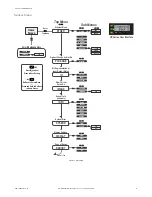
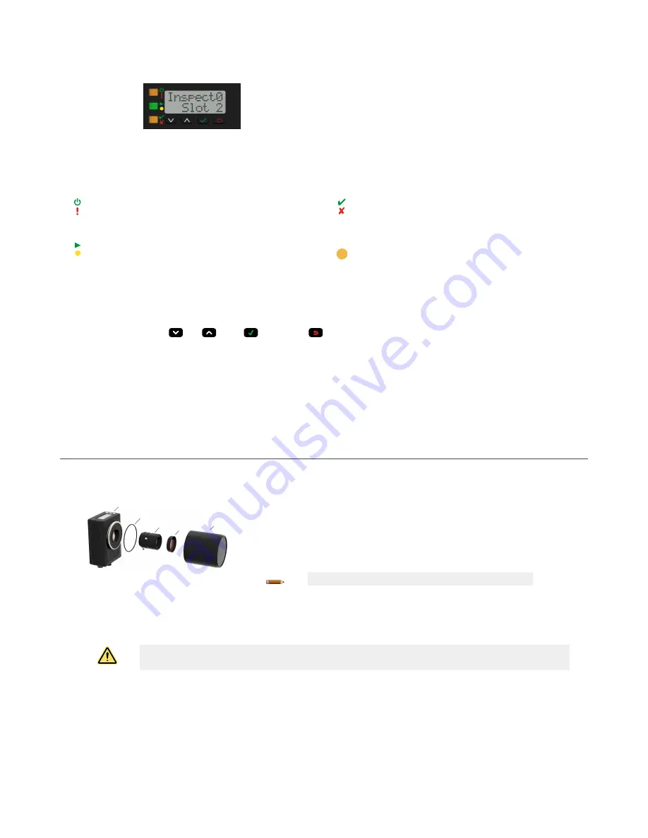
Figure 3. Install the Accessories
1. VE sensor
2. O-ring (used with the sealed lens cover)
3. C-mount lens (available separately)
4. Filter (optional)
5. Sealed lens cover (optional)
An external light (optional) is not shown.
Note: A sealed lens cover and a ring light cannot be used together.
1. If you are using a sealed lens cover: Remove the black thread protector (not shown) from the sensor (1).
2. If you are using a sealed lens cover: Fit a single o-ring (2) into the undercut area behind the sensor threads.
3. Remove the yellow temporary imager cover (not shown) from the sensor.
CAUTION: Do not remove the imager cover until you are ready to install the lens. Do not touch the imager. Dirt or dust
on the imager can affect sensing reliability.
4. Remove any protective covers from the lens. Handle the lens carefully to avoid smudges and dirt on the optical elements.
5. Thread the lens (3) onto the sensor.
6. Make sure that the lens is focused; see
7. Use the thumbscrews on the lens to lock the focus and aperture rings and to prevent movement that can occur during cleaning or
accidental contact.
8. If you are using a filter: Thread the filter (4) onto the front of the C-mount lens.
9. If you are using a linear polarization filter: Rotate the outer portion of the filter mount to determine the position where glare is reduced the
most, and use the locking thumbscrew to fasten the filter in position.
10. If you are using a sealed lens cover: Thread the sealed lens cover (5) onto the threaded portion of the sensor.
11. Or, if you are using an external light bracket: Attach an external light bracket to the sensor using the provided hardware kit.
VE Series Smart Camera
2
www.bannerengineering.com - Tel: +1-763-544-3164
P/N 191667 Rev. G


