3.
From Sensor Neighborhood, click
to connect to the desired sensor.
The status changes from Available
to Connected
and the
Sensor screen displays. Click
to disconnect from the sensor.
4. If the desired sensor is not listed, verify that:
•
The network adapter connected to the sensor has the same subnet mask as the sensor (for example, 192.168.0.xxx); view the subnet
mask in the Network Adapters list at
Home > Sensor Neighborhood > Network Adapters
•
The Ethernet cable is the correct type
•
The TCP/IPv4 settings are correct
Or, manually enter the sensor's IP address.
Note: The sensor's IP address and subnet mask are also available from the sensor display.
Sensor Screen
The
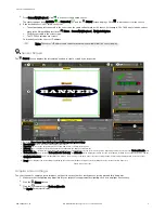
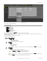
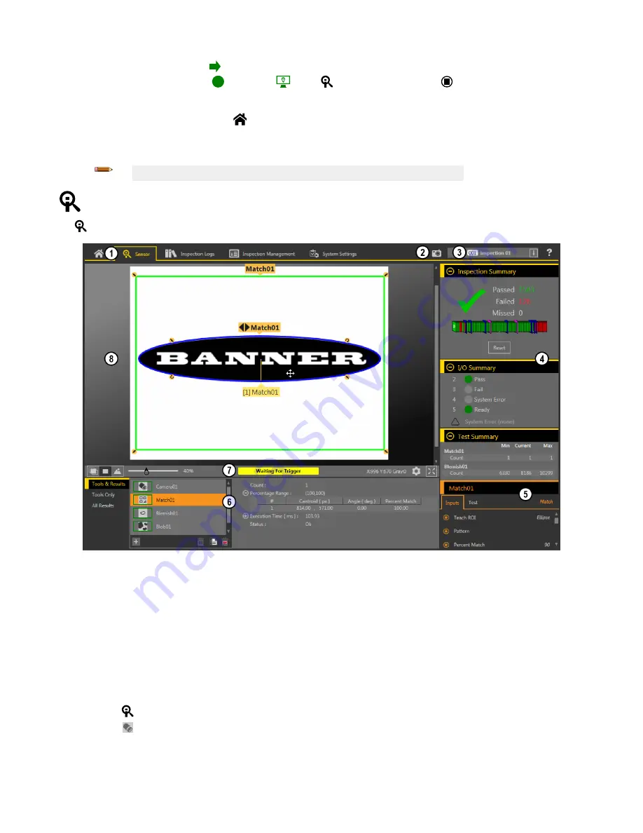
Sensor screen displays the information needed to create or modify an inspection.
1. Screens—Home, Sensor, Inspection Logs, Inspection Management, System Settings
2. Manual Trigger button—Click to manually trigger the sensor
3. Inspection list—Select the desired inspection to start, and to view or modify the inspection
4. Summary pane—Includes the Inspection Summary, the I/O Summary, and the Test Summary
5. Parameters pane—Includes user-adjustable Inputs parameters or Test parameters for the tools in an inspection, depending on what is selected in the Tools and Results pane
6. Tools and Results pane—Includes Tools and Results, Tools Only, and All Results, which display the camera tool, the tools that are included in the current inspection, and the
results of the inspection
7. Image Pane Parameters panel—Includes ROI view buttons, zoom, x and y coordinates, grayscale value, settings button, and full image display button, as well as sensor
messages
8. Image pane—Displays the current image captured by the sensor; this includes the region of interest (ROI) for the tool for the selected inspection
Figure 9. Sensor Screen
Acquire a Good Image
The sensor needs to capture a good image of each part to ensure that it correctly passes good parts and fails bad parts.
1. Make sure that the lighting is appropriate for your target. Use supplementary lighting, such as a ring light, if necessary.
2.
Click the
Sensor screen.
3.
Click the
camera tool on Tools and Results.
The Inputs parameters display.
VE Series Smart Camera
P/N 191667 Rev. G
www.bannerengineering.com - Tel: +1-763-544-3164
5


