
4. Set the trigger.
a) Expand the Trigger parameters.
b) In the Trigger Mode list, click Internal (continuous images).
5. Run Auto Exposure.
a) Expand the Imager parameters.
b) Expand the Auto Exposure parameters, and click Start to run.
6. Check the lighting on the part.
•
Make sure that the lighting is constant and consistent (unchanging over time, no shadows or hot spots)
•
Capture the shape and form of the target object with lighting that optimizes its contrast and separates the feature of interest from the
background. Depending on the target, consider other Banner lights
•
Adjust the mounting angle to provide the clearest image of the part features you are inspecting
7. After checking and adjusting the lighting, run Auto Exposure a second time or adjust the exposure manually by expanding the Exposure
parameters and moving the slider or entering a specific exposure time.
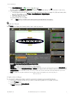
8. Adjust the focus.
a) Place the part so that the area to be focused appears in the center of the Image pane.
b) Expand the Focus Info parameters.
c) Make sure that the Focus Info checkbox is selected.
d) Adjust the focus of the lens while monitoring the focus number.
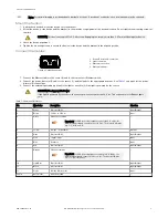
The focus number is a number between 1 and 255. Use the Image pane to determine when the image is sharp enough, or use the focus
number as a guide. Turn the focus ring on the lens until the focus number is at the highest possible number between 1 and 255. The
focus number is also available on the sensor display.
Note: There is no optimal value for this number, but it can be used as a guide if you are setting up more than one
sensor that are focused on the same target.
e) Tighten the locking thumbscrews to secure the lens at the desired focus.
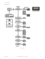
Set Up an Inspection
Vision Manager allows you to set up or make changes to an inspection while the sensor is running. Changes are automatically saved as they are
made.
1.
From the
Sensor screen, click
in the upper right corner to view the inspection list.
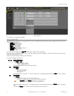
2. Click Add New Inspection.
A new inspection is added to the list, the Image pane updates, and the Tools & Results tab shows only the camera tool.
3. Add tools and adjust them as needed for the inspection.
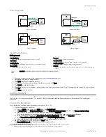
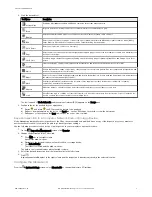
Add a Tool
1.
Click
on the Tools & Results tab.
The Add Tool window opens.
VE Series Smart Camera
6
www.bannerengineering.com - Tel: +1-763-544-3164
P/N 191667 Rev. G