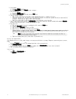
background image

3.

From Sensor Neighborhood, click 

 to connect to the desired sensor.

The status changes from Available 

 to Connected 

 and the 

 Sensor screen displays. Click 

 to disconnect from the sensor.

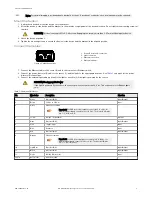
4. If the desired sensor is not listed, verify that:

The network adapter connected to the sensor has the same subnet mask as the sensor (for example, 192.168.0.xxx); view the subnet
mask in the Network Adapters list at 

 Home > Sensor Neighborhood > Network Adapters

The Ethernet cable is the correct type

The TCP/IPv4 settings are correct

Or, manually enter the sensor's IP address.

Note: The sensor's IP address and subnet mask are also available from the sensor display.
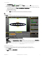
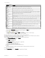
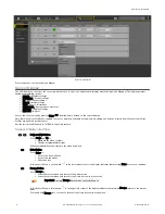
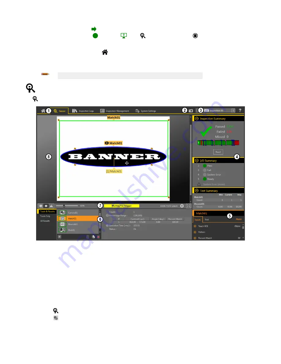
 Sensor Screen

The 

 Sensor screen displays the information needed to create or modify an inspection.

1. Screens—Home, Sensor, Inspection Logs, Inspection Management, System Settings
2. Manual Trigger button—Click to manually trigger the sensor
3. Inspection list—Select the desired inspection to start, and to view or modify the inspection
4. Summary pane—Includes the Inspection Summary, the I/O Summary, and the Test Summary
5. Parameters pane—Includes user-adjustable Inputs parameters or Test parameters for the tools in an inspection, depending on what is selected in the Tools and Results pane
6. Tools and Results pane—Includes Tools and Results, Tools Only, and All Results, which display the camera tool, the tools that are included in the current inspection, and the

results of the inspection

7. Image Pane Parameters panel—Includes ROI view buttons, zoom, x and y coordinates, grayscale value, settings button, and full image display button, as well as sensor

messages

8. Image pane—Displays the current image captured by the sensor; this includes the region of interest (ROI) for the tool for the selected inspection

Figure 9. Sensor Screen

Acquire a Good Image

The sensor needs to capture a good image of each part to ensure that it correctly passes good parts and fails bad parts.

1. Make sure that the lighting is appropriate for your target. Use supplementary lighting, such as a ring light, if necessary.
2.

Click the 

 Sensor screen.

3.

Click the 

camera tool on Tools and Results.

The Inputs parameters display.

VE Series Smart Camera


P/N 191667 Rev. G

www.bannerengineering.com - Tel: +1-763-544-3164

5

Summary of Contents for VE Series

Page 1: ...an energized or de energized sensor output condition CAUTION Electrostatic Discharge Avoid the damage that electrostatic discharge ESD can cause to the Sensor Always use a proven method for preventin...

Page 2: ...nt levels of access to the tools and data Installation Instructions Install the Accessories 1 2 3 5 4 Figure 3 Install the Accessories 1 VE sensor 2 O ring used with the sealed lens cover 3 C mount le...

Page 3: ...discrete I O connections 3 Connect the external light cable optional to the light connection 2 if the light is powered by the sensor CAUTION Use Appropriate Power If the light is powered by the sensor...

Page 4: ...stem settings a popup window may appear prompting to allow Vision Manager to make changes to your computer Click Yes 7 Click Close to exit the installer Getting Started Power up the sensor and verify...

Page 5: ...n Summary the I O Summary and the Test Summary 5 Parameters pane Includes user adjustable Inputs parameters or Test parameters for the tools in an inspection depending on what is selected in the Tools...

Page 6: ...heckbox is selected d Adjust the focus of the lens while monitoring the focus number The focus number is a number between 1 and 255 Use the Image pane to determine when the image is sharp enough or us...

Page 7: ...points and lines for use as inputs to other tools Logic Uses Boolean logic to combine or convert tool results or to drive discrete outputs from tool results Logic tool data can be used to evaluate th...

Page 8: ...ion Manual p n 191666 for more information Sensor Display Interface Down and Up Buttons Press Down and Up to Navigate the menu systems Change programming settings When navigating the menu systems the...

Page 9: ...INK SUBNET GATEWAY STATUS IP PSELECT TRIGGER INPUT MAC MAX SPD By NUM OUTPUT FW VER BOOT NAME MODEL HOUR SERIAL SLEEP VIEW Ethernet Menu Product Change by Slot No Bit Representation of Input Output St...

Page 10: ...itle merchantability data loss non interference with or non infringement of any intellectual property rights or the accuracy reliability quality or content in or linked to the services Banner and its...

Page 11: ...OF PROFITS OR ANY INCIDENTAL CONSEQUENTIAL OR SPECIAL DAMAGES RESULTING FROM ANY PRODUCT DEFECT OR FROM THE USE OR INABILITY TO USE THE PRODUCT WHETHER ARISING IN CONTRACT OR WARRANTY STATUTE TORT ST...

Reviews: