•
Phillip head screws (4)
•
Set screw (1)
•
Disc (1)
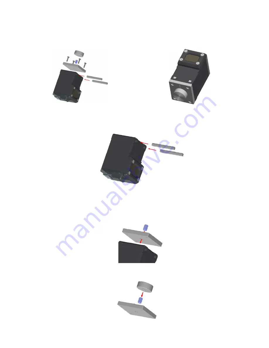
Figure 5. BWA-Q45VA-FESS bracket and Q45VA assembly exploded view
Screw Retainers
Disc
Base Plate
Figure 6. Final assembly
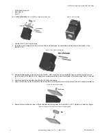
1. Flip the Q45VA / VAC upside down.
2. Insert the screw retainers into the two slots of the device and align the screw holes with the holes at the bottom of the
Q45VA / VAC.
Figure 7. Insert the screw retainers
Screw Retainers
3. Position the base plate on the bottom of the Q45VA / VAC so that the four counterbores face up and the alignment mark
faces the front of the Q45VA / VAC. Align the counterbores with the holes at the bottom of the device. See
on page
2.
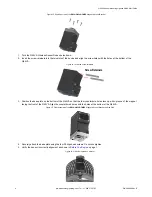
4. Securely attach the base plate using the four Phillips head screws.
5. Apply Loctite to the center screw hole of the base plate. Secure the set screw into the center hole until it reaches resistance.
Figure 8. Secure the set screw
Set Screw
6. Fasten the disc on the set screw, with the threaded side facing away from the Q45VA / VAC. Tighten only with your fingers.
Figure 9. Fasten the disc onto the set screw and finger tighten
Disc
Q45VA Sensor Mounting Options Quick Start Guide
2
www.bannerengineering.com - Tel: + 1 888 373 6767
P/N 208986 Rev. E

