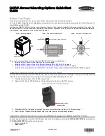
Figure 13. Exploded view of the BWA-Q45VA-CMSS Magnetic Mount Bracket
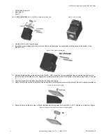
1. Turn the Q45VA Wireless Sensor Node upside down.
2. Insert the screw retainers into the two slots of the device and align the screw holes with the holes at the bottom of the
Q45VA.
Figure 14. Insert the screw retainers
Screw Retainers
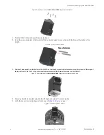
3. Position the base plate on the bottom of the Q45VA so that the four counterbore holes face up with v-groove of the magnet
facing the front of the Q45VA. Align the counterbored holes with the holes at the bottom of the Q45VA.
Figure 15. Final assembly of the BWA-Q45VA-CMSS Magnetic Mount Bracket and the Q45
4. Securely attach the base plate using the four Phillips head screws. Do not overtighten.
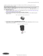
5. Verify the sensor is correctly alignment as shown in
on page 1.
Figure 16. Q45VA mounted on a motor
Q45VA Sensor Mounting Options Quick Start Guide
4
www.bannerengineering.com - Tel: + 1 888 373 6767
P/N 208986 Rev. E


